
Page 318 - Build Your Own Transistor Radios a Hobbyists Guide to High-Performance and Low-Powered Radio Circuits
P. 318
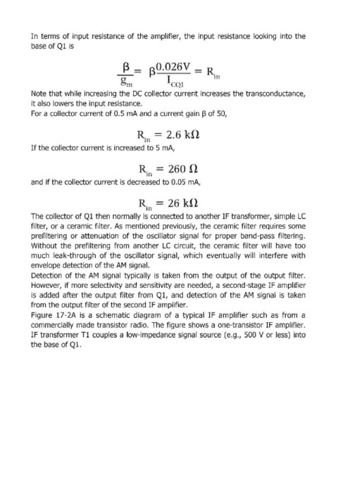
In terms  of input resistance  of the  amplifier,  the  input  resistance  looking  into  the

            base of Ql is


                                                =  (З _.-
                                                                             i )


            Note that while  increasing  the IDC  collector current increases the transconductance,
            it also lowers the input resistance.
            For а collector current of 0.5  тА and  а current gain  ~ of 50,


                                                              , .

                                                     J
            If the collector current is increased to 5 тА,


            and  if the collector current is decreased to 0.05  тА,


                                                     il
            The collector of Ql then  погmаllу is connected to another IF transformer, simple LC
            filter,  ог а ceramicfilter.  As  тепtiопеd previously,  the ceramic filter requires  some

            prefiltering  ог attenuation  of the  oscillator  signal  for  р!горег band-pass  filtering.
            Without  the  prefiltering  from  another  LC  circuit,  the  ceгamic filter  will  have  too
            much  leak-through  of the  oscillator  signal,  which  еvепtuаllу will  iпtеrfеге with
            envelope dеtесtiоп of the АМ signal.
            Detection  of th.e  АМ sigпа l  typically  is  taken  from  the  output of the  output  filter.
            However,  if тоге selectivity and  sепsitivity аге needed,  а second-stage IF ampHfier

            is  added  after the  output filter  from  Ql,  and  detection  of the  АМ sigпаl  is  taken
            from  the output filter of the second IF amplifier.
            Figure  17-2А is  а schematic  diagram  of  а typical  IF  amplifier  such  as  from  а
            commercially made transistor radio.  The  figure shows  а one-transistor IF amplifier.
            IF tгапsfогmег Тl couples  а lоw-imреdапсе signal  source  (e.g.,  500 V ог less)  iпtо

            the base of Ql.