
Page 319 - Build Your Own Transistor Radios a Hobbyists Guide to High-Performance and Low-Powered Radio Circuits
P. 319
+V IF Transformer
С
8 4
В
6 IIF Signall
0.1 uf J А 5 ~ 1
Т2
CN
Ccbl
IF Transformer
5 1 2 ГО
3 4 9 (е . 9 . ,2 N 3 9 04 )
О1
+ Vbias
....
Т1 VE
R:E
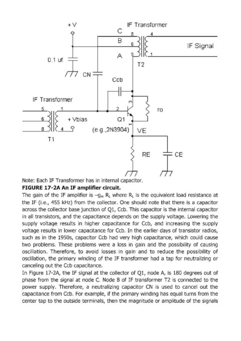
Note: Each IF Transformer has in internal capacitor.
FIGURE 17-2А Ап IF amplifier circuit.
The gain of the IF amplifier is -gm R L where R L is the equivalent load resistance at
the IF (i.e., 455 kHz) from the collector. Опе should note that there is а capacitor
across the collector base junction of Ql, СсЬ. This capacitor is the internal capacitor
in all transistors, and the capacitance d'epends оп the supplyvoltage. Lowering the
supply voltage results in higher capacitance far СсЬ, and increasing the supply
voltage results in lower capacitance for СсЬ. In the earlier days of tгапsistог radios,
such asin the 1950s, capacitor СсЬ had very high capacitance, which could cause
two probIems. These probIems were а loss in gain and the possibility of саusiпg
oscillation. Therefore, to avoid losses in gain and to reduce the possibility of
oscillation, the primary winding of the IF transformer had а tap for neutralizing ог
canceling out the СсЬ capacitance.
Iп Figure 17-2А, the IF signal at the collector of Q1, node А, is 180 degrees out of
phase from the signal at node С. Node В of IF transfor,mer Т2 is connected to the
power supply. Therefore, а neutralizing capacitor CN is used to сапсеl out the
capacitance from СсЬ. For example, if the primary winding has equal turns from the
centeг tap to the outside teгminals, then the magnitude ог amplitude of the signals