
Page 311 - Build Your Own Transistor Radios a Hobbyists Guide to High-Performance and Low-Powered Radio Circuits
P. 311
М1
"'- х "- Filter 1 Fiilter_ 1 Out
-
/ / "
/
/1
Oscillator Signal О Degree
Cosine Signal
Input Si gnal
"-
/
Sum_IQ (t)
М2
"- Х "- Filter 2 Fiilter_ 20ut
-
/ / "
/
l'
Oscillator Signal 90 Degrees
Sine Signal
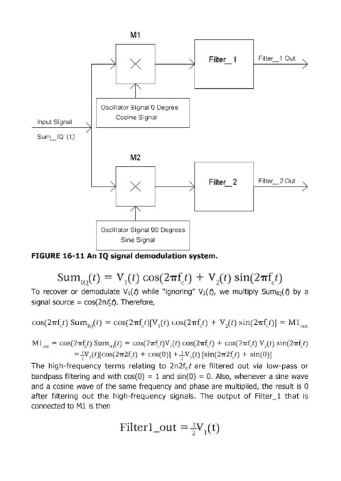
FIGURE 16-11 Ап IQ signal demodu!lation system.
= т
То recover ог demodulate V 1 (f) while "ignoring" V 2 (f), we multiply SumIQ(t} Ьу а
signal source = соs(2пfcf) . Therefore,
il1 2'11 c:t)] = 1
ош
Ml{)U( = о · 21Т(/) um t . 21Тf/) I t 21Тf/) + 21Тfг.t) 2 () in(2'Пf/
lQ
= ~. 'I(t)[ " 21'1"2 /) + (] + ~ " 1 t [ in(21Т2 / ) + "in( ]
The high-frequency terms relating to 2п2f t аге filtered out via low-pass ог
с
bandpass filtering and with cos(O) = 1 and sin(O) = о. Also, whenever а sine wave
and а cosine wave of the same frequency and phase аге multiplied, the result is О
after filtering out the high-frequency signals. The output of Filter _1 th,at is
connected to М1 isthen
.
1
2