
Page 38 - Build Your Own Transistor Radios a Hobbyists Guide to High-Performance and Low-Powered Radio Circuits
P. 38
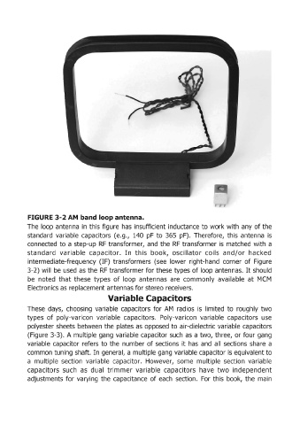
FIGURE 3-2 AM  band loop antenna.

            The  loop antenna  in  this figure  has  insufficient inductance to work with  any of the
            standard  variable  capacitors  (e.g.,  140  pF  to  365  pF).  Therefore,  this  antenna  is
            connected  to a step-up  RF  transformer,  and  the  RF  transformer is  matched  with  a
            standard  variable  capacitor.  In  this  book,  oscillator  coils  and/or  hacked
            intermediate-frequency  (IF)  transformers  (see  lower  right-hand  corner  of Figure
            3-2) will  be  used  as  the  RF transformer for these types of loop antennas.  It should

            be  noted  that  these  types  of  loop  antennas  are  commonly  available  at  MCM
            Electronics as replacement antennas for stereo receivers.
                                            Variable Capacitors

            These  days,  choosing  variable  capacitors  for  AM  radios  is  limited  to  roughly  two
            types  of poly-varicon  variable  capacitors.  Poly-varicon  variable  capacitors  use
            polyester sheets  between the plates as  opposed  to air-dielectric variable capacitors
            (Figure  3-3).  A multiple gang  variable capacitor such  as  a two, three,  or four gang

            variable  capacitor  refers  to the  number of sections  it has  and  all  sections  share  a
            common tuning shaft. In general, a multiple gang variable capacitor is equivalent to
            a  multiple  section  variable  capacitor.  However,  some  multiple  section  variable
            capacitors  such  as  dual  trimmer  variable  capacitors  have  two  independent
            adjustments  for  varying  the  capacitance  of each  section.  For  this  book,  the  main