
Page 39 - Build Your Own Transistor Radios a Hobbyists Guide to High-Performance and Low-Powered Radio Circuits
P. 39
tuning capacitor is described as an "x" gang variable capacitor or equivalently, an
"x" section variable capacitor.
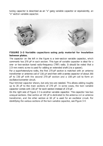
FIGURE 3-3 Variable capacitors using poly material for insulation
between plates.
The capacitor on the left in the figure is a twin-section variable capacitor, which
commonly has 270 pF in each section. This type of variable capacitor is ideal for a
one- or two-section tuned radio-frequency (TRF) radio. It should be noted that a
2.S-mm metric screw is used for adding an extended shaft (via a spacer).
For a superheterodyne radio, the first 270-pF section is matched with an antenna
transformer or antenna coil of 330 IJH and then with a series capacitor of about 300
pF to 330 pFwith the second 270-pF section and a 180-IJH coil to form an
oscillator/converter circuit.
Four trimmer capaCitor shown, but only two are needed. This allows adding roughly
up to 20 pF to the main sections of 270 pF. In some cases, the twin variable
capacitor comes with 330 pF for each section instead of 270 pF.
On the right side of Figure 3-3 is another variable capacitor. This capacitor has two
unequal sections. One section at 140 pF is dedicated to the antenna coil or antenna
transformer, and the other section at 60 pF is used for an oscillator circuit. For
identifying the various sections of the twin variable capacitor, see Figure 3-4.