
Page 68 - Build Your Own Transistor Radios a Hobbyists Guide to High-Performance and Low-Powered Radio Circuits
P. 68
5
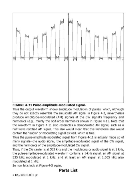
FIGURE 4-11 Pulse-amplitude-modulated signal.
Thus the output waveform shows amplitude modulation of pulses, which, although
they do not exactly resemble the sinusoidal AM signal in Figure 4-3, nevertheless
produce amplitude-modulated (AM) signa.ls at the CW signal's frequency and
harmonics (e.g., mainly the odd-order harmonics shown in Figure 4-11. Note that
the waveform in Figure 4-11 also resembles a demodulated AM' signal, such as a
half-wave-reetified AM signal. This also would mean that this waveform also would
contain the "audio" or modulating signal as well, which is true.
Thus the pulse-amplitude-modulated signal from Figure 4-11 is actually made up of
many signals-the audio signal, the amplitude-modulated signal of the CW signal,
and the harmonics of the amplitude-modulated CW signal.
Thus, if the CW carrier is at 535 kHz and the modulating or audio signal is at 1 kHz,
the pulse-amplitude-modulated waveform contains a 1-kHz signal, an AM signal at
535 kHz modulated at 1 kHz, and at least an AM signal at 1,605 kHz also
modulated at 1 kHz.
So now let's look at Figure 4-5 again.
Parts List
• Cl, C3: 0.001 ~F