
Page 64 - Build Your Own Transistor Radios a Hobbyists Guide to High-Performance and Low-Powered Radio Circuits
P. 64
multiturn pot. Also, the waveform symmetry of a 74HCT14 (or 74ACT14) inverter
oscillator circuit is not as close to a 50 percent duty cycle as the 74HC14 (or
74AC14) part.
Modulator Circuit for the CW Generator
The type of amplitude modulator that is used is known as a transistor drain
modulation (Figure 4-7). U2A (74HCOS) is an inverter gate with an open-drain
output. This means that the output is a short circuit to ground when the input (pin
1) is logic high and an open circuit when the input to U2A is logic low.
+ 5
C9
~ AM Signal (e .g .. 537 KHz or 535 KHz)
1 uf ~_2=-----+------iC~
ON Signal
0.01 uf
R6
R4
4700
100 K
R5
5 ~_~6 __ ~ ____ ~~ ____ ~ ____ ~ Vmod
1 K
1lli 1
0.01 Urn ca
C5.T
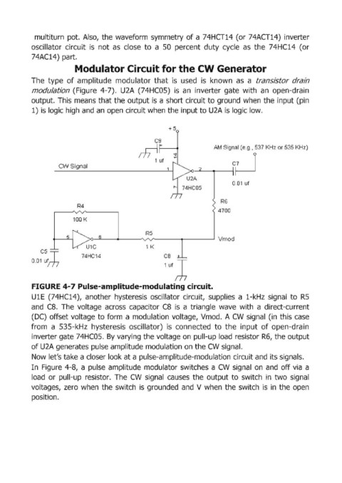
FIGURE 4-7 Pulse-amplitude-modulating circuit.
U lE (74HC14), another hysteresis oscillator circuit, supplies a l-kHz signal to R5
and CB. The voltage across capacitor CB is a triangle wave with a direct-current
(DC) offset voltage to form a modulation voltage, Vmod. A CW signal (in this case
from a 53S-kHz hysteresis oscillator) is connected to the input of open-drain
inverter gate 74HCOS. By varying the voltage on pull-up load resistor R6, the output
of U2A generates pulse amplitude modulation on the CW signal.
Now let's take a closer look at a pulse-amplitude-modulation circuit and its signals.
In Figure 4-8, a pulse amplitude modulator switches a CW signal on and off via a
load or pull-up resistor. The CW signal causes the output to switch in two signal
voltages, zero when the switch is grounded and V when the switch is in the open
position.