
Page 62 - Build Your Own Transistor Radios a Hobbyists Guide to High-Performance and Low-Powered Radio Circuits
P. 62
V,. 535 KHz CW
R2 POT lK
R' 74HC14 .,
1200 ., R'
elO e,
• lutn 100 m1 Ah1535 KHZ
'"'
V'A V2A
0.01 uf
74HC 14 74HC05
e'i
0.001 ul \iReg_l ., RS
R4
7805T 4700
e12
100 K
ell 'of
)o--"------J __ ~R,,'~-,--___1 V~d
'of
e, v,e
'of 1
74HC14 e8
.. 9to .. 20
455 KHz CW R7
Ah1455 KHz
R13 i
4700 ."
RII ew
1800 R12 POT
'K VIE 100
74HC14 0.01 uf
455 KHIAM Test 51g
R8
C4
VIF V2F 20K 470 pr 1 C13
e',,;r 74HC14 74HC05 Cl R' 0.01 ut
0 .001~
330 un 20K
RIO
e2
4700
0.0018 uf
FIGURE 4-5 Schematic of the test generator.
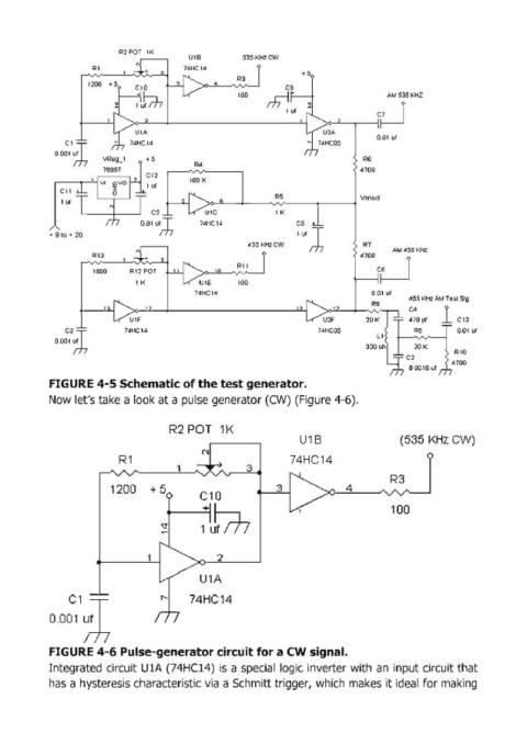
Now let's take a look at a pulse generator (CW) (Figure 4-6).
R2 POT 1K
U1B (535 KHz CW)
R1 '" 74HC14
1 3
R3
1200 +5 3 4
C10
100
"<t 1+utn
~
1 2
U1A
C1 ,,~ 74HC14
0.001 ~
FIGURE 4-6 Pulse-generator circuit for a CW signal.
Integrated circuit U1A (74HC14) is a special logic inverter with an input circuit that
has a hysteresis characteristic via a Schmitt trigger, which makes it ideal for making