
Page 61 - Build Your Own Transistor Radios a Hobbyists Guide to High-Performance and Low-Powered Radio Circuits
P. 61
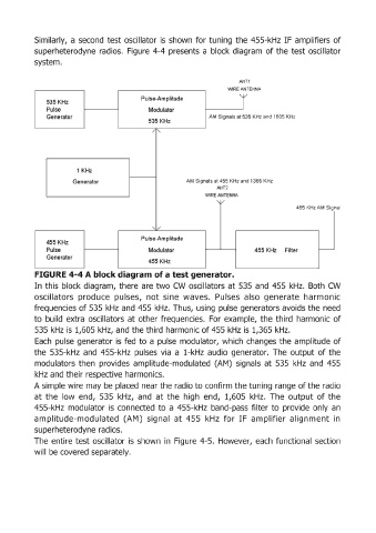
Similarly,  a second  test oscillator  is  shown  for tuning  the 455-kHz  IF amplifiers of

            superheterodyne  radios.  Figure  4-4  presents  a  block  diagram  of the  test oscillator
            system.


                                                                             ANTl
                                                                         WIRE ANTENNA
                                              Pulse-Am plitude
                535 KHz                                                      T
                Pulse                           Modulator
                Generator                                          AM  Signals at 535 KHz and 1605 KHz
                                                535 KHz


                         1 KHz

                        Generator                           AM Signals at 455 KHz and 1365 KHz
                                                                      ANT2
                                                                  WIRE ANTENNA
                                                                      '\V
                                                                                               455 KHz AM Signal


                                              Pulse-Am plitude
                455 KHz
                Pulse                           Modulator                         455 KHz   Filter
                Generator
                                                455 KHz

            FIGURE 4-4 A block diagram of a test generator.
            In this  block  diagram,  there  are  two  CW  oscillators at 535  and  455  kHz.  Both  CW
            oscillators  produce  pulses,  not  sine  waves.  Pulses  also  generate  harmonic
            frequencies of 535  kHz  and  455  kHz.  Thus,  using  pulse generators avoids the need
            to  build  extra  oscillators  at other frequencies.  For  example,  the  third  harmonic of

            535  kHz is  1,605 kHz, and the third harmonic of 455 kHz is  1,365 kHz.
            Each  pulse  generator  is fed  to a pulse  modulator,  which  changes  the  amplitude of
            the  535-kHz  and  455-kHz  pulses  via  a  l-kHz  audio  generator.  The  output of the
            modullators  then  provides  amplitude-modulated  (AM)  signals  at  535  kHz  and  455

            kHz and their respective harmonics.
            A simple wire may be placed  near the radio to confirm the tuning range of the radio
            at  the  low  end,  535  kHz,  and  at the  high  end,  1,605  kHz.  The  output  of the
            455-kHz  modulator  is  connected  to  a 455-kHz  band-pass  filter to  provide  only  an
            amplitude-modulated  (AM)  signal  at  455  kHz  for  IF  amplifier  alignment  in
            superheterodyne radios.

            The  entire test oscillator  is  shown  in  Figure  4-5.  However,  each  functional  section
            will be covered separately.