
Page 58 - Build Your Own Transistor Radios a Hobbyists Guide to High-Performance and Low-Powered Radio Circuits
P. 58
Chapter 4
Building Simple Test Oscillators and Modulators
Before any of the radios are presented, it would be preferable to build some simple
test equipment. This chapter introduces the amplitude Imodulated (AM) signal and
various ways to generate radio-frequency (RF) and intermediate-frequency (IF)
signa! ls for testing radio projects.
The Continuous-Wave Signal
A continuous-wave signal is defined by a fixed amplitude and a fixed frequency. In
an audio continuous-wave signal, this is better known as a tone.
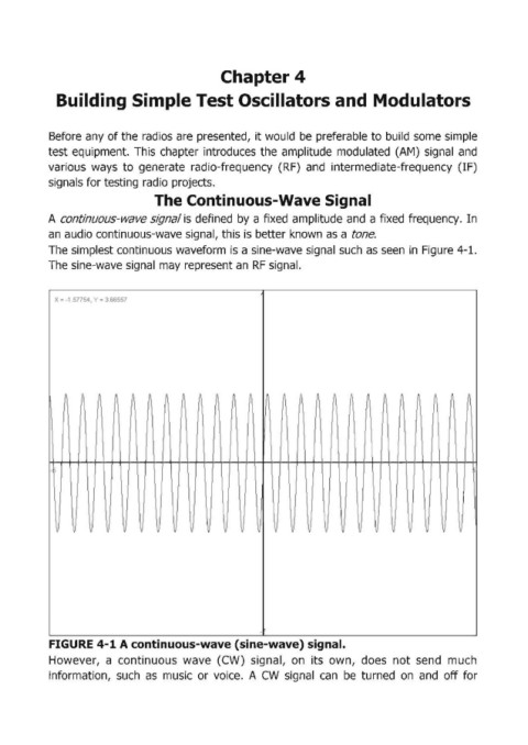
The simplest continuous waveform is a sine-wave signal such as seen in Figure 4-l.
The sine-wave signal may represent an RF signal.
X'" -1 .sn54. Y '" 3.66557
~ ~ i\ n J\ A h n .1 A " A A f\ I ~ ~ i\ ~ A " It
1\ ! I
,
.
i I
I
I '
I
v U v V v y v v y \I 'I V V V v V v If y 11 v v lJ
-
FIGURE 4-1 A continuous-wave (sine-wave) signal.
However, a continuous wave (CW) signal, on its own, does not send much
information, such as music or voice. A CW signal can be turned on and off for