Page 60 - Build Your Own Transistor Radios a Hobbyists Guide to High-Performance and Low-Powered Radio Circuits
P. 60

)(  '" 1 .35027, Y '" 3 .02306


                                                                 ~
                                                                     A
                                              A                                                            A
               ~                          ~                                 A                          It
                   ~                                                            A
                       A              A                                             A          A ~
                           A  ~   A                                                     A   A
                                                                      I                        I


                                    I

                         V   V                             I   I                      V   V v
                     v              V   v                  I                  )   V              v
                 U                                                  I         ~                      v
                                            V                                                            v
              v
                                                    v


                                                            -
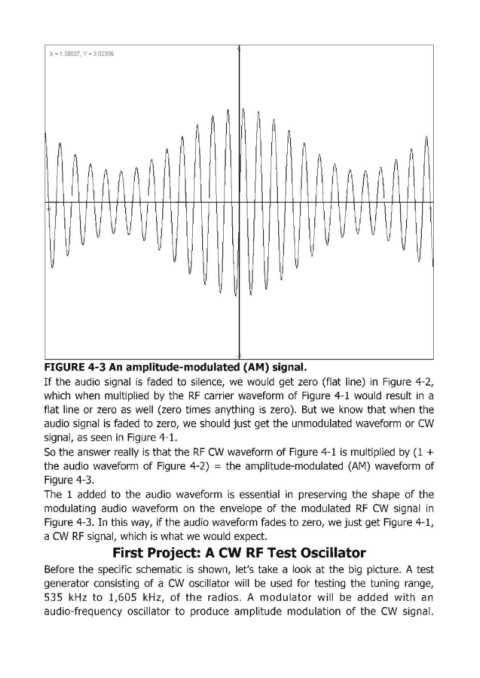
            FIGURE 4-3 An amplitude-modulated (AM) signal.

            If the audio signal  is faded  to  silence,  we  would  get zero  (flat  line)  in  Figure  4-2,
            which when  multiplied  by  the  RF  carrier waveform  of Figure  4-1  would result  in  a
            flat  line  or zero  as  well  (zero  times  anything  is  zero).  But we  know  that when  the
            audio signal  is faded to zero,  we  should just get the unmodulated  waveform  or CW

            signal, as seen  in  Figure 4-1.
            So the answer really is that the RF CW waveform of Figure 4-1  is multiplied  by (1  +
            the audio  waveform  of Figure  4-2)  = the  amplitude-modulated  (AM)  waveform  of
            Figure 4-3.
            The  1 added  to  the  audio  waveform  is  essential  in  preserving  the shape  of the
            modulating  audio  waveform  on the  envelope  of the  modulated  RF  CW  signal  in

            Figure 4-3. In this way,  if the audio waveform fades to zero, we just get Figure 4-1,
            a CW RF signal, which is what we would  expect.
                             First Project: A CW RF Test Oscillator

            Before  the  specific schematic  is  shown,  let's take  a look  at the  big  picture.  A test
            generator  consisting  of a CW  oscillator  will  be  used  for testing  the  tuning  range,
            535  kHz  to  1,605  kHz,  of the  radios.  A  modulator  will  be  added  with  an
            audio-frequency  oscillator  to  produce  amplitude  modulation  of the  CW  signal.
   55   56   57   58   59   60   61   62   63   64   65