
Page 130 - Build a Remote Controlled Robot
P. 130
SKIN AND FINISHING TOUCHES
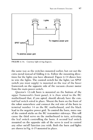
FIGURE 6-14. Courtesy light wiring diagram. 97
the same way as the switches mounted earlier, but cut out the
extra metal instead of folding it in. Follow the mounting direc-
tions for the lights you have obtained. Figure 6-14 shows how
to wire the lights. The control switch for the lights (an SPST
switch you must supply) is mounted on the rear of the lower
framework on the opposite side of the vacuum cleaner motor
from the main power switch.
Questor’s 12-volt horn is mounted on the bottom of the
upper framework’s front panel; it is then wired to the RC
motherboard that, if you opted, should already have the con-
trol leaf switch wired in place. Mount the horn on the front of
the robot somewhere and connect the red wire of the horn to
terminal number 14 on the RC motherboard, and the black
lead to the negative power grid. To control the horn, move one
of the control sticks on the RC transmitter sideways. This will
cause the third servo on the motherboard to turn, activating
the leaf switch controlling the horn. A second leaf switch
mounted on the opposite side of the servo is used to control
any other on/off function you wish. Both the horn and lights
are shown in Fig. 6-15 mounted in place.