
Page 125 - Build a Remote Controlled Robot
P. 125
92
CHAPTER SIX
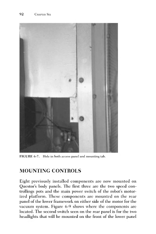
FIGURE 6-7. Hole in both access panel and mounting tab.
MOUNTING CONTROLS
Eight previously installed components are now mounted on
Questor’s body panels. The first three are the two speed con-
trollings pots and the main power switch of the robot’s motor-
ized platform. These components are mounted on the rear
panel of the lower framework on either side of the motor for the
vacuum system. Figure 6-9 shows where the components are
located. The second switch seen on the rear panel is for the two
headlights that will be mounted on the front of the lower panel