
Page 48 - Build a Remote Controlled Robot
P. 48
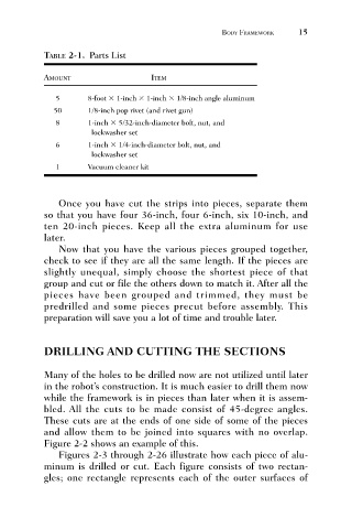
TABLE 2-1. Parts List
                              AMOUNT                    ITEM             BODY FRAMEWORK     15

                                 5       8-foot   1-inch   1-inch   1/8-inch angle aluminum
                                50       1/8-inch pop rivet (and rivet gun)
                                 8       1-inch   5/32-inch-diameter bolt, nut, and
                                          lockwasher set
                                 6       1-inch   1/4-inch-diameter bolt, nut, and
                                          lockwasher set
                                 1       Vacuum cleaner kit


                                 Once you have cut the strips into pieces, separate them
                              so that you have four 36-inch, four 6-inch, six 10-inch, and
                              ten 20-inch pieces. Keep all the extra aluminum for use
                              later.
                                 Now that you have the various pieces grouped together,
                              check to see if they are all the same length. If the pieces are
                              slightly unequal, simply choose the shortest piece of that
                              group and cut or file the others down to match it. After all the
                              pieces have been grouped and trimmed, they must be
                              predrilled and some pieces precut before assembly. This
                              preparation will save you a lot of time and trouble later.


                              DRILLING AND CUTTING THE SECTIONS


                              Many of the holes to be drilled now are not utilized until later
                              in the robot’s construction. It is much easier to drill them now
                              while the framework is in pieces than later when it is assem-
                              bled. All the cuts to be made consist of 45-degree angles.
                              These cuts are at the ends of one side of some of the pieces
                              and allow them to be joined into squares with no overlap.
                              Figure 2-2 shows an example of this.
                                 Figures 2-3 through 2-26 illustrate how each piece of alu-
                              minum is drilled or cut. Each figure consists of two rectan-
                              gles; one rectangle represents each of the outer surfaces of