
Page 62 - Build a Remote Controlled Robot
P. 62
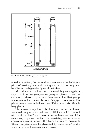
FIGURE 2-23. Drilling and cutting guide.   BODY FRAMEWORK     29


                              aluminum section, first write the correct number or letter on a
                              piece of masking tape and then apply the tape to its proper
                              location according to the figure of that piece.
                                 After all the pieces have been prepared they must again be
                              separated into two groups—one group of pieces for each of
                              the two sections of Questor’s framework. The first group,
                              when assembled, forms the robot’s upper framework. The
                              pieces needed are as follows: four 36-inch- and six 10-inch-
                              long pieces.
                                 The second group forms the lower section of the frame-
                              work and the pieces needed are: ten 20-inch and four 6-inch
                              pieces. Of the ten 20-inch pieces for the lower section of the
                              robot, only eight are needed. The remaining two are used as
                              connecting pieces between the lower and upper framework.
                              These two pieces can be identified by the letters A and B
                              which you should have marked on them.