
Page 64 - Build a Remote Controlled Robot
P. 64
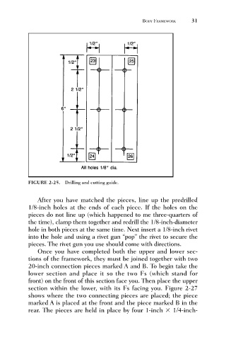
FIGURE 2-25. Drilling and cutting guide.   BODY FRAMEWORK     31


                                 After you have matched the pieces, line up the predrilled
                              1/8-inch holes at the ends of each piece. If the holes on the
                              pieces do not line up (which happened to me three-quarters of
                              the time), clamp them together and redrill the 1/8-inch-diameter
                              hole in both pieces at the same time. Next insert a 1/8-inch rivet
                              into the hole and using a rivet gun “pop” the rivet to secure the
                              pieces. The rivet gun you use should come with directions.
                                 Once you have completed both the upper and lower sec-
                              tions of the framework, they must be joined together with two
                              20-inch connection pieces marked A and B. To begin take the
                              lower section and place it so the two Fs (which stand for
                              front) on the front of this section face you. Then place the upper
                              section within the lower, with its Fs facing you. Figure 2-27
                              shows where the two connecting pieces are placed; the piece
                              marked A is placed at the front and the piece marked B in the
                              rear. The pieces are held in place by four 1-inch   1/4-inch-