
Page 113 - Buried Pipe Design
P. 113
Design of Gravity Flow Pipes 89
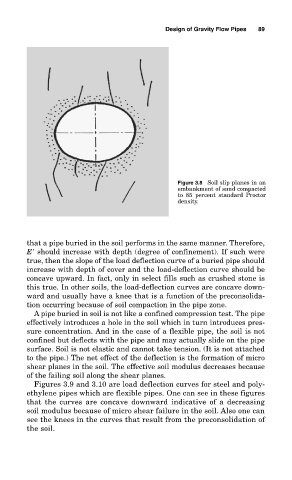
Figure 3.8 Soil slip planes in an
embankment of sand compacted
to 85 percent standard Proctor
density.
that a pipe buried in the soil performs in the same manner. Therefore,
E should increase with depth (degree of confinement). If such were
true, then the slope of the load deflection curve of a buried pipe should
increase with depth of cover and the load-deflection curve should be
concave upward. In fact, only in select fills such as crushed stone is
this true. In other soils, the load-deflection curves are concave down-
ward and usually have a knee that is a function of the preconsolida-
tion occurring because of soil compaction in the pipe zone.
A pipe buried in soil is not like a confined compression test. The pipe
effectively introduces a hole in the soil which in turn introduces pres-
sure concentration. And in the case of a flexible pipe, the soil is not
confined but deflects with the pipe and may actually slide on the pipe
surface. Soil is not elastic and cannot take tension. (It is not attached
to the pipe.) The net effect of the deflection is the formation of micro
shear planes in the soil. The effective soil modulus decreases because
of the failing soil along the shear planes.
Figures 3.9 and 3.10 are load deflection curves for steel and poly-
ethylene pipes which are flexible pipes. One can see in these figures
that the curves are concave downward indicative of a decreasing
soil modulus because of micro shear failure in the soil. Also one can
see the knees in the curves that result from the preconsolidation of
the soil.