
Page 190 - Buried Pipe Design
P. 190
164 Chapter Three
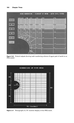
Figure 3.46 Printed output showing node numbering scheme of upper part of mesh in an
FEA model.
Figure 3.47 Photograph of a PC monitor display of the FEA mesh.