
Page 309 - Buried Pipe Design
P. 309
280 Chapter Five
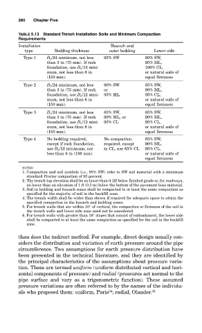
TABLE 5.13 Standard Trench Installation Soils and Minimum Compaction
Requirements
Installation Haunch and
type Bedding thickness outer bedding Lower side
Type 1 D o /24 minimum, not less 95% SW 90% SW,
than 3 in (75 mm). If rock 95% ML,
foundation, use D o /12 mini- 100% CL,
mum, not less than 6 in or natural soils of
(150 mm). equal firmness
Type 2 D o /24 minimum, not less 90% SW 85% SW,
than 3 in (75 mm). If rock or 90% ML,
foundation, use D o /12 mini- 95% ML 95% CL,
mum, not less than 6 in or natural soils of
(150 mm). equal firmness
Type 3 D o /24 minimum, not less 85% SW, 85% SW,
than 3 in (75 mm). If rock 90% ML, or 90% ML,
foundation, use D o /12 mini- 95% CL 95% CL,
mum, not less than 6 in or natural soils of
(150 mm). equal firmness
Type 4 No bedding required, No compaction 85% SW,
except if rock foundation, required, except 90% ML,
use D o /12 minimum, not in CL, use 85% CL 95% CL,
less than 6 in (150 mm). or natural soils of
equal firmness
NOTES:
1. Compaction and soil symbols (i.e., 95% SW) refer to SW soil material with a minimum
standard Proctor compaction of 95 percent.
2. The trench top elevation shall be no lower than 0.1H below finished grade or, for roadways,
no lower than an elevation of 1 ft (0.3 m) below the bottom of the pavement base material.
3. Soil in bedding and haunch zones shall be compacted to at least the same compaction as
specified for the majority of soil in the backfill zone.
4. The trench width shall be wider than shown if required for adequate space to attain the
specified compaction in the haunch and bedding zones.
5. For trench walls that are within 10° of vertical, the compaction or firmness of the soil in
the trench walls and lower side zone need not be considered.
6. For trench walls with greater than 10° slopes that consist of embankment, the lower side
shall be compacted to at least the same compaction as specified for the soil in the backfill
zone.
than does the indirect method. For example, direct design usually con-
siders the distribution and variation of earth pressure around the pipe
circumference. Two assumptions for earth pressure distribution have
been presented in the technical literature, and they are identified by
the principal characteristics of the assumptions about pressure varia-
tion. These are termed uniform (uniform distributed vertical and hori-
zontal components of pressure) and radial (pressures act normal to the
pipe surface and vary as a trigonometric function). These assumed
pressure variations are often referred to by the names of the individu-
34
als who proposed them: uniform, Paris ; radial, Olander. 32