
Page 308 - Buried Pipe Design
P. 308
Rigid Pipe Products 279
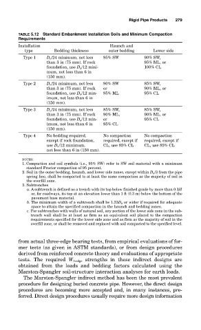
TABLE 5.12 Standard Embankment Installation Soils and Minimum Compaction
Requirements
Installation Haunch and
type Bedding thickness outer bedding Lower side
Type 1 D o /24 minimum, not less 95% SW 90% SW,
than 3 in (75 mm). If rock 95% ML, or
foundation, use D o /12 mini- 100% CL
mum, not less than 6 in
(150 mm).
Type 2 D o /24 minimum, not less 90% SW 85% SW,
than 3 in (75 mm). If rock or 90% ML, or
foundation, use D o /12 min- 95% ML 95% CL
imum, not less than 6 in
(150 mm).
Type 3 D o /24 minimum, not less 85% SW, 85% SW,
than 3 in (75 mm). If rock 90% ML, 90% ML, or
foundation, use D o /12 min- or 95% CL
imum, not less than 6 in 95% CL
(150 mm).
Type 4 No bedding required, No compaction No compaction
except if rock foundation, required, except if required, except if
use D o /12 minimum, CL, use 85% CL CL, use 85% CL
not less than 6 in (150 mm).
NOTES:
1. Compaction and soil symbols (i.e., 95% SW) refer to SW soil material with a minimum
standard Proctor compaction of 95 percent.
2. Soil in the outer bedding, haunch, and lower side zones, except within D o /3 from the pipe
spring line, shall be compacted to at least the same compaction as the majority of soil in
the overfill zone.
3. Subtrenches
a. A subtrench is defined as a trench with its top below finished grade by more than 0.1H
or, for roadways, its top at an elevation lower than 1 ft (0.3 m) below the bottom of the
pavement base material.
b. The minimum width of a subtrench shall be 1.33D o or wider if required for adequate
space to attain the specified compaction in the haunch and bedding zones.
c. For subtrenches with walls of natural soil, any portion of the lower side zone in the sub-
trench wall shall be at least as firm as an equivalent soil placed to the compaction
requirements specified for the lower side zone and as firm as the majority of soil in the
overfill zone, or shall be removed and replaced with soil compacted to the specified level.
from actual three-edge bearing tests, from empirical evaluations of for-
mer tests (as given in ASTM standards), or from design procedures
derived from reinforced concrete theory and evaluations of appropriate
tests. The required W 3-edge strengths in these indirect designs are
obtained from the loads and bedding factors calculated using the
Marston-Spangler soil-structure interaction analyses for earth loads.
The Marston-Spangler indirect method has been the most prevalent
procedure for designing buried concrete pipe. However, the direct design
procedures are becoming more accepted and, in many instances, pre-
ferred. Direct design procedures usually require more design information