
Page 44 - CNC Robotics
P. 44
Chapter 2 / Electronics
L 298
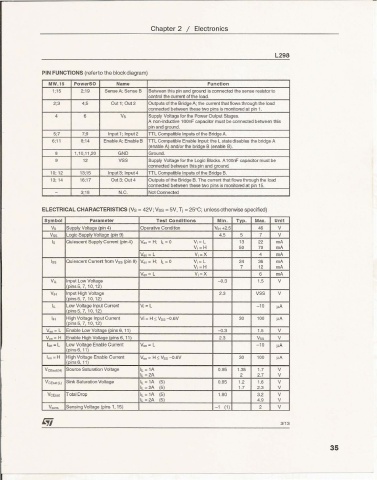
PIN FUNCTIONS (referto the block diagram)
MW. 15 Po werSO Name Functi on
1;15 2;19 Sense A: Sense B Between this pin and grounj is connected the sense reestor to
contra the currert of the load
2;3 4;5 Out 1; Oul2 Outputs altha Bridge A; the current that flows through the load
connected between these two pins is monitored at pin 1.
4 6 Vs Supply Voltage for the Power Ou tput Stages.
A I'lOIl-indu:tive 100n F capacik:lr must be oonnecled between this
pin and groll"ld.
5;7 7:9 Inp ut 1; InpuI 2 TTL comoauae Inputs of the Bridge A-
6;11 8;14 Enable A; Enable B TTL Compa'ble Enable Input the l stale disables the bridge A
(enaJj e A) ancVor the bri:lge B (enable B).
• 1,10,11,20 GND Ground.
9 12 VSS SUpp¥ Voltage for the l og ic Blocks . A1oarr capacior must be
conneded between this pin and ground
10: 12 13;15 Inpul3: Input 4 TIL Comoatible loo uts of the Bridge 8.
13; 14 16;17 OUI3;OuI4 Outp uts 01the Bridge 8. The currere that flows Ihroughthe loa::l
connected between these two pins is mooitoredat pin 15.
- 3;18 N.C. Not Connected
ELECTRICAL CHA RACTE RISTICS (Vs =42V; Vss =SV, Tj =25°C; unless otherwise specified)
Sym bol Parameter T es t Conditions Min . Typ. Max . Un it
V, Supp ly Voltage (pin 4) Operative ccnonco V,to! +2.5 46 V
Vss Logic Supply Voltage (pin 9) 4 5 5 7 V
I, Oulescerr Supply Cu rrent (pin 4) V Qn _ H; <_0 V;_ L 13 22 mA
VI= H 50 70 mA
Van= L V,=X 4 mA
Iss Qu iescert Current from Vss (pin 9) Ven- H: IL - 0 V _ L 24 36 mA
i
VI = H 7 12 mA
Yen = L V,= X 6 mA
V,L Input Low Voltage -0.3 1.5 V
(pins 5. 7,1 0, 12)
V" Input High Voltage 2.3 VSS V
(pins5.7, 10. 12)
" Low Vollage Input Cu rrert Vi = L -10 ""
(pinsS. 7. 10. 12)
I. High Voltage Input Current Vi = H s Vss --o.6V 30 100 "A
(pinsS,7, 10, 12)
V",, _ L Enable l ow Voltage (pins 6, 11) -0.3 1.5 V
V.... =H Enable High Voltage (pins 6. 11) 2.3 V" V
len_ l l ow Voltage Enabl e Current Veo-l 10
(pins 6,1 1) ""
I,." _ H High Voltage Enable Current Ven- H s vse 0.6V 30 100 "A
(pins6.11)
VCEsaHH) Source Saturation Voltage I L - 1A 0.95 1.35 1.7 V
IL= 2A 2 2.7 V
VCENI(l ) Sink Saturation Voltage 1t.-1A (5) O.BS 1.2 1.6 V
IL- 2A (5) 1.7 2.3 V
VeE,.. Total Drop 1t. -1A (5) 1.80 3.2 V
IL -2A (5) 49 V
V_ Sensing Voltage (pins 1, 15) - 1 (1) 2 V
3113
35
---- ----------------- ------