
Page 48 - CNC Robotics
P. 48
Chapter 2 / Electronics
L298
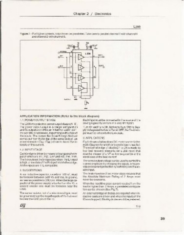
Figure 7 : For highercurrents,outputscan be paralleled.Take care to parallel channel 1 with channel 4
and channel2 with channel3.
.rnFI u---t ~.~
4
ENABl£ •
.., N- use err,
~
.., , • "'''
11:::=
" N.
" "
~
• t::l ~
L1=-
..
.i '5L..-- 1
~~.
L.
A PPLICATION INFORMATION (R efer to the block diagram)
1.1. POWEROUTPUTSTAGE Each input must be connectedto the sourceaf the
TheL298i ntegratestwopoweroutputstages(A; B). driving signals by means of a very short path.
The power output stage is a bridge configuration Turn-On and Turn-Off : Before to Tum -ONthe Sup-
and its outputs can drive an inductiveload in com- plyVoltageand beforeto TurnitOFF,the Enablein-
manor differenzialmode, dependingon the state of put must be driven to the Low state.
the inputs. The current that flowsthrough the load
comesout fromthe bridgeat the sense output: an 3. APPLI CATIONS
externalresistor (AsA;Rse.) allows todetectthe in- Fig 6 showsa bidirectional DC motor controlSche-
tensityol this current. matic Diagram for which only onebridgeisneeded.
The externalbridge of diodes 01 to 04 is made by
1.2. INPUT STAGE
four fast recovery elements (trr :5 200 nsec) that
Eachbridgeis drivenby meansof fourgatesthe in- must be chosen of a VF as low as possible at the
put of whichare In1 ; 1n2 ; EnA and In3 ; In4 ; EnS. worstcase of the load current.
The Ininputsset thebridge state whenThe En input
Thesenseoutputvoltagecan be usedtoco ntrolthe
ishigh;a lowslateof theEninputinhibitsthebridge. current amplitude by choppingthe inputs,or to pro-
All the inputs are TIL corroatible.
videovercurrentprotectionby switchinglowtheen-
2. SUGGESTIONS able input.
A non inductive capacitor, usuallyof 100 nF. must The brake function (Fast motor stop) requires that
be foreseen between both Vs and Vss, to ground, the Absolute Maximum Rating of 2 Amps must
as nearas possibletoGNDpin.Whenthe largeca- neverbe overcome.
pacitorof the powersupply is too far fromthe IC, a Whenthe repetitivepeak current needed from the
second smaller one must be foreseen near the loadis higherthan 2 Amps,a paralleledconfigura-
L298. tion can be chosen (See Fig.7).
The sense resistor,not of a wire woundtype , must An externalbridge of diodes are required when ln-
be groundednear the negativepoleof Vsthat must duetive loadsare drivenand whenthe inputsof the
be nearthe GND pin of the I.C. ICarechopped; Shottkydiodeswouldbepreferred.
7/13
39