
Page 166 - Cam Design Handbook
P. 166
THB5 8/15/03 1:53 PM Page 154
154 CAM DESIGN HANDBOOK
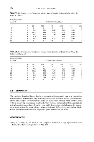
TABLE 5.10 Displacement Constraints, Missing Values Supplied by Interpolating Along the
Rows of Table 5.9
Cam translation
s 2 (mm) Cam rotation f 2 (deg.)
0 50120180235 315 360
0 0 0 0 0 0 0 0
5 0 0.03 0.20 0.88 0.21 0.02 0
18 0 00.53 3.01 4.38 3.700.400
25 0 0.61 4.03 5.00 4.09 0.45 0
33 0 0.50 3.31 4.12 3.48 0.37 0
43 0 0.07 0.38 0.62 0.52 0.07 0
50 0 0 0 00 0 0 0
TABLE 5.11 Displacement Constraints, Missing Values Supplied by Interpolating Along the
Columns of Table 5.9
Cam translation
s 2 (mm) Cam rotation f 2 (deg)
0 50120180235 315 360
0 0 0 0 0 0 0 0
5 0 0.03 0.20 1.68 0.21 0.02 0
18 0 00.53 3.04 4.38 3.700.400
25 0 0.61 4.03 5.00 4.43 0.45 0
33 0 0.50 3.31 4.12 3.48 0.37 0
43 0 0.07 1.10 0.62 0.52 0.17 0
50 0 0 0 00 0 0 0
5.6 SUMMARY
The methods described here afford a convenient and systematic means of developing
motion curves. As illustrated they work very well in the face of numerous constraints and
enable the designer to conveniently refine the synthesized motion when needed, often
without modifying basic design constraints. Only familiar numerical methods are required
to implement the procedures. Handling nonrigid followers is a bit challenging for design-
ers who are unfamiliar with splines and the solution of differential equations but should
not be beyond the reach of most engineers, given a little time and effort.
REFERENCES
Akiba, K., Shimizu, A., and Sakai. H., “A Comparison Simulation of High Speed Driven Valve
Trains,” SAE Technical Paper Series 810865, 1981.