Page 202 - Cam Design Handbook
P. 202

THB7  8/15/03  1:58 PM  Page 190

          190                      CAM DESIGN HANDBOOK


                                  N

                                               g


                                   B         A
                                                              C

                                   r(q)
                      s(y)                  q

                                              y

                                O                              F


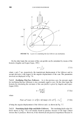
                      FIGURE 7.6.  Layout of a translating flat-face follower cam mechanism.


             On the other hand, the curvature of the cam profile can be calculated by means of the
          formula (Angeles and Lopez-Cajun, 1991)
                                            1
                                       k =                              (7.31)
                                           ss
                                            + ¢¢
          where s and s≤ are, respectively, the translational displacement of the follower and its
          second derivative with respect to the angular displacement of the cam. The parameters
          involved are displayed in Fig. 7.6.
          7.4.2.2 Oscillating Flat-Face Followers.  As in the previous case, the pressure angle
          for oscillating flat-face followers is also constantly equal to zero. On the other hand, the
          formula for calculating the curvature of the cam profile is given by Angeles and Lopez-
          Cajun (1991)
                                          (1 + f¢) 3
                                       k =                             (7.32a)
                                           F  y ()
          where
                                                                e
                                                          2
                                                    e +
                      F y () ∫ f¢¢cos f + (1 +  f¢) ( [ 1 2 f¢)sin f + ( 1  f¢) ],  e ∫  (7.32b)
                                          +
                                                                l
          f being the angular displacement of the follower and e as shown in Fig. 7.7.
          7.4.2.3  Translating Knife-Edge and Roller Followers.  The translating knife-edge fol-
          lower  shown  in  Fig.  7.8  is  not  usually  found  in  practice,  because  of  the  large  contact
          stresses that it produces. However, it has theoretical and practical importance because its
   197   198   199   200   201   202   203   204   205   206   207