
Page 288 - Cam Design Handbook
P. 288
THB9 9/19/03 7:26 PM Page 276
276 CAM DESIGN HANDBOOK
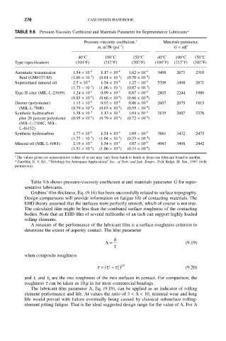
TABLE 9.6 Pressure-Viscosity Coefficient and Materials Parameter for Representative Lubricants*
Pressure-viscosity coefficient, † Materials parameter,
-1
2
a, m /N (psi ) G = aE¢
40°C 100°C 150°C 40°C 100°C 150°C
Type (specification) (104°F) (212°F) (302°F) (104°F) (212°F) (302°F)
Automatic transmission 1.54 ¥ 10 -8 1.17 ¥ 10 -8 1.02 ¥ 10 -8 3498 2673 2310
-4
-4
-4
fluid (GM6137-M) (1.06 ¥ 10 ) (0.81 ¥ 10 ) (0.70 ¥ 10 )
Superrefined mineral oil 2.5 ¥ 10 -8 1.54 ¥ 10 -8 1.27 ¥ 10 -8 5709 3498 2871
-4
-4
-4
(1.73 ¥ 10 ) (1.06 ¥ 10 ) (0.87 ¥ 10 )
Type II ester (MIL-L-23699) 1.24 ¥ 10 -8 0.99 ¥ 10 -8 0.87 ¥ 10 -8 2805 2244 1980
-4
-4
-4
(0.85 ¥ 10 ) (0.68 ¥ 10 ) (0.60 ¥ 10 )
Diester (polyolester) 1.15 ¥ 10 -8 0.93 ¥ 10 -8 0.80 ¥ 10 -8 2607 2079 1815
-4
-4
-4
(MIL-L-7808) (0.79 ¥ 10 ) (0.63 ¥ 10 ) (0.55 ¥ 10 )
Synthetic hydrocarbon 1.38 ¥ 10 -8 1.13 ¥ 10 -8 1.04 ¥ 10 -8 3135 2607 2376
-4
-4
plus 20 percent polyolester (0.95 ¥ 10 ) (0.79 ¥ 10 ) (0.72 ¥ 10 )
-4
(MIL-L-2104C, MIL-
L-46152)
Synthetic hydrocarbon 1.77 ¥ 10 -8 1.51 ¥ 10 -8 1.09 ¥ 10 -8 3861 3432 2475
-4
-4
-4
(1.77 ¥ 10 ) (1.04 ¥ 10 ) (0.75 ¥ 10 )
Mineral oil (MIL-L-6081) 2.19 ¥ 10 -8 1.54 ¥ 10 -8 1.07 ¥ 10 -8 4983 3498 2442
-4
-4
-4
(1.51 ¥ 10 ) (1.06 ¥ 10 ) (0.74 ¥ 10 )
†
The values given are representative values of a and may vary from batch to batch or from one lubricant brand to another.
*Zaretbhy, E. V. Ed., “Tribology for Aerospace Apptications” Soc. of Treb. and Lub. Emgrs., Park Ridge, Ill. See., 1997 (with
permission).
Table 9.6 shows pressure-viscosity coefficient a and materials parameter G for repre-
sentative lubricants.
Grubins’ film thickness, Eq. (9.16) has been successfully related to surface topography.
Design comparisons will provide information on fatigue life of contacting materials. The
EHD theory assumed that the surfaces were perfectly smooth, which of course is not true.
The calculated film might be less than the combined surface roughness of the contacting
bodies. Note that an EHD film of several millionths of an inch can support highly loaded
rolling elements.
A measure of the performance of the lubricant film is a surface-roughness criterion to
determine the extent of asperity contact. The film parameter
h
L= (9.19)
t
when composite roughness
t = ( t + t ) 12 (9.20)
2
2
1
2
and t 1 and t 2 are the rms roughness of the two surfaces in contact. For comparison, the
roughness t can be taken as 10m in for most commercial bearings.
The lubricant film parameter L, Eq. (9.19), can be applied as an indicator of rolling
element performance and life. At values the ratio of 3 <L< 10, minimal wear and long
life would prevail with failure eventually being caused by classical subsurface rolling-
element pitting fatigue. That is the ideal suggested design range for the value of L. For L