
Page 46 - Cam Design Handbook
P. 46
THB2 8/15/03 12:48 PM Page 34
34 CAM DESIGN HANDBOOK
which depends on its flexibility. In other words, we have a “bump” in the contour that
neither a roller nor other follower could follow. This curve is therefore impractical for a
DRD cam.
2.5 MODIFIED CONSTANT VELOCITY CURVE
WITH CIRCULAR ARCS
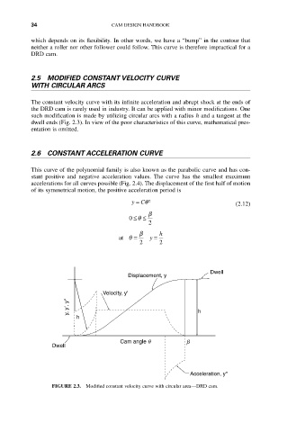
The constant velocity curve with its infinite acceleration and abrupt shock at the ends of
the DRD cam is rarely used in industry. It can be applied with minor modifications. One
such modification is made by utilizing circular arcs with a radius h and a tangent at the
dwell ends (Fig. 2.3). In view of the poor characteristics of this curve, mathematical pres-
entation is omitted.
2.6 CONSTANT ACCELERATION CURVE
This curve of the polynomial family is also known as the parabolic curve and has con-
stant positive and negative acceleration values. The curve has the smallest maximum
accelerations for all curves possible (Fig. 2.4). The displacement of the first half of motion
of its symmetrical motion, the positive acceleration period is
y = Cq 2 (2.12)
b
0 ££
q
2
b h
at q = y =
2 2
Dwell
Displacement, y
Velocity, y'
y, y', y" h
h
Cam angle q b
Dwell
Acceleration, y"
FIGURE 2.3. Modified constant velocity curve with circular area—DRD cam.