
Page 58 - Cam Design Handbook
P. 58
THB2 8/15/03 12:48 PM Page 46
46 CAM DESIGN HANDBOOK
the cam calculations for displacement, velocity, and acceleration of the follower, tabulated
data for the cycloidal curve are shown in Appendix B.
2.12 DOUBLE HARMONIC MOTION CURVE
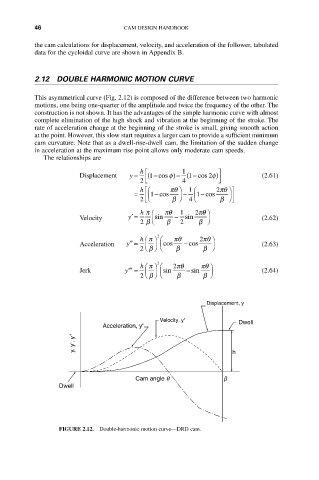
This asymmetrical curve (Fig. 2.12) is composed of the difference between two harmonic
motions, one being one-quarter of the amplitude and twice the frequency of the other. The
construction is not shown. It has the advantages of the simple harmonic curve with almost
complete elimination of the high shock and vibration at the beginning of the stroke. The
rate of acceleration change at the beginning of the stroke is small, giving smooth action
at the point. However, this slow start requires a larger cam to provide a sufficient minimum
cam curvature. Note that as a dwell-rise-dwell cam, the limitation of the sudden change
in acceleration at the maximum rise point allows only moderate cam speeds.
The relationships are
h È 1 ˘
Displacement y = (1 - cos f ) - (1 cos 2f ) (2.61)
-
2 Í Î 4 ˙ ˚
h Ê È pq ˆ 1 Ê 2pq ˆ˘
= Í Á1 - cos ˜ - Á1 - cos ˜ ˙
2 Î Ë b ¯ 4 Ë b ¯ ˚
h p Ê pq 1 2pq ˆ
Velocity y ¢ = Ásin - sin ˜ (2.62)
2 b Ë b 2 b ¯
2
h p pq 2pq ˆ
Ê ˆ Ê
Acceleration y ¢¢ = Á ˜ Ácos - cos ˜ (2.63)
Ë ¯ Ë
2 b b b ¯
h p 3 2pq pq ˆ
Ê ˆ Ê
Jerk y ¢¢¢ = Á ˜ Ásin - sin ˜ (2.64)
Ë ¯ Ë
2 b b b ¯
Displacement, y
Velocity, y' Dwell
Acceleration, y"
y, y', y" h
Cam angle q b
Dwell
FIGURE 2.12. Double-harmonic motion curve—DRD cam.