
Page 97 - Carbonate Sedimentology and Sequence Stratigraphy
P. 97
88 WOLFGANG SCHLAGER
0 m
FST
200 m 20 km
FST
400 m
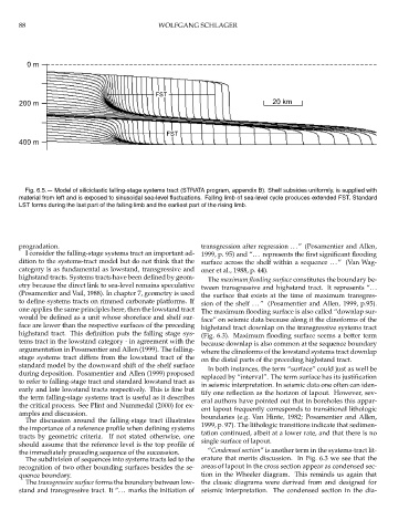
Fig. 6.5.— Model of siliciclastic falling-stage systems tract (STRATA program, appendix B). Shelf subsides uniformly, is supplied with
material from left and is exposed to sinusoidal sea-level fluctuations. Falling limb of sea-level cycle produces extended FST. Standard
LST forms during the last part of the falling limb and the earliest part of the rising limb.
progradation. transgression after regression ...” (Posamentier and Allen,
I consider the falling-stage systems tract an important ad- 1999, p. 95) and “... represents the first significant flooding
dition to the systems-tract model but do not think that the surface across the shelf within a sequence ...” (Van Wag-
category is as fundamental as lowstand, transgressive and oner et al., 1988, p. 44).
highstand tracts. Systems tracts have been defined by geom- The maximum flooding surface constitutes the boundary be-
etry because the direct link to sea-level remains speculative tween transgressive and highstand tract. It represents “...
(Posamentier and Vail, 1988). In chapter 7, geometry is used the surface that exists at the time of maximum transgres-
to define systems tracts on rimmed carbonate platforms. If
sion of the shelf ...” (Posamentier and Allen, 1999, p.95).
one applies the same principles here, then the lowstand tract The maximum flooding surface is also called “downlap sur-
would be defined as a unit whose shoreface and shelf sur- face” on seismic data because along it the clinoforms of the
face are lower than the respective surfaces of the preceding highstand tract downlap on the transgressive systems tract
highstand tract. This definition puts the falling stage sys- (Fig. 6.3). Maximum flooding surface seems a better term
tems tract in the lowstand category - in agreement with the because downlap is also common at the sequence boundary
argumentation in Posamentier and Allen (1999). The falling- where the clinoforms of the lowstand systems tract downlap
stage systems tract differs from the lowstand tract of the on the distal parts of the preceding highstand tract.
standard model by the downward shift of the shelf surface
In both instances, the term “surface” could just as well be
during deposition. Posamentier and Allen (1999) proposed
replaced by “interval”. The term surface has its justification
to refer to falling-stage tract and standard lowstand tract as
in seismic interpretation. In seismic data one often can iden-
early and late lowstand tracts respectively. This is fine but
tify one reflection as the horizon of lapout. However, sev-
the term falling-stage systems tract is useful as it describes
eral authors have pointed out that in boreholes this appar-
the critical process. See Plint and Nummedal (2000) for ex-
ent lapout frequently corresponds to transitional lithologic
amples and discussion. boundaries (e.g. Van Hinte, 1982; Posamentier and Allen,
The discussion around the falling-stage tract illustrates
1999, p. 97). The lithologic transitions indicate that sedimen-
the importance of a reference profile when defining systems
tation continued, albeit at a lower rate, and that there is no
tracts by geometric criteria. If not stated otherwise, one
single surface of lapout.
should assume that the reference level is the top profile of
the immediately preceding sequence of the succession. “Condensed section” is another term in the systems-tract lit-
The subdivision of sequences into systems tracts led to the erature that merits discussion. In Fig. 6.3 we see that the
recognition of two other bounding surfaces besides the se- areas of lapout in the cross section appear as condensed sec-
quence boundary. tion in the Wheeler diagram. This reminds us again that
The transgressive surface forms the boundary between low- the classic diagrams were derived from and designed for
stand and transgressive tract. It “... marks the initiation of seismic interpretation. The condensed section in the dia-