
Page 24 - Centrifugal Pumps 2E
P. 24
12 Centrifugal Pumps: Design and Application
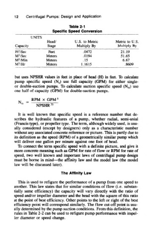
Table 2-1
Specific Speed Conversion
UNITS
Head/ U.S. to Metric Metric to U.S.
Capacity Stage Multiply By Multiply By
3
Ft /Sec Feet .0472 21.19
3
M /Sec Meters .0194 51.65
3
M /Min Meters ,15 6.67
3
M /Hr Meters 1.1615 .8609
but uses NPSHR values in feet in place of head (H) in feet. To calculate
pump specific speed (N s) use full capacity (GPM) for either single-
or double-suction pumps. To calculate suction specific speed (N ss) use
one half of capacity (GPM) for double-suction pumps.
It is well known that specific speed is a reference number that de-
scribes the hydraulic features of a pump, whether radial, semi-axial
(Francis type), or propeller type. The term, although widely used, is usu-
ally considered (except by designers) only as a characteristic number
without any associated concrete reference or picture. This is partly due to
its definition as the speed (RPM) of a geometrically similar pump which
will deliver one gallon per minute against one foot of head.
To connect the term specific speed with a definite picture, and give it
more concrete meaning such as GPM for rate of flow or RPM for rate of
speed, two well known and important laws of centrifugal pump design
must be borne in mind—the affinity law and the model law (the model
law will be discussed later).
The Affinity Law
This is used to refigure the performance of a pump from one speed to
another. This law states that for similar conditions of flow (i.e. substan-
tially same efficiency) the capacity will vary directly with the ratio of
speed and/or impeller diameter and the head with the square of this ratio
at the point of best efficiency. Other points to the left or right of the best
efficiency point will correspond similarly. The flow cut-off point is usu-
ally determined by the pump suction conditions. From this definition, the
rules in Table 2-2 can be used to refigure pump performance with impel-
ler diameter or speed change.