
Page 379 - Centrifugal Pumps 2E
P. 379
344 Centrifugal Pumps: Design and Application
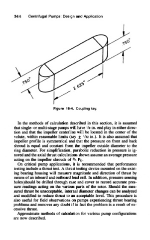
Figure 16-4. Coupling key.
In the methods of calculation described in this section, it is assumed
]
that single- or multi-stage pumps will have /4-in. end play in either direc-
tion and that the impeller centerline will be located in the center of the
volute, within reasonable limits (say ± '/32 in.)- It is also assumed that
impeller profile is symmetrical and that the pressure on front and back
shroud is equal and constant from the impeller outside diameter to the
ring diameter. For simplification, parabolic reduction in pressure is ig-
nored and the axial thrust calculations shown assume an average pressure
3
acting on the impeller shrouds of /4 P D.
On critical pump applications, it is recommended that performance
testing include a thrust test. A thrust testing device mounted on the exist-
ing bearing housing will measure magnitude and direction of thrust by
means of an inboard and outboard load cell. In addition, pressure sensing
holes should be drilled through case and cover to record accurate pres-
sure readings acting on the various parts of the rotor. Should the mea-
sured thrust be unacceptable, internal diameter changes can be analyzed
and modified to reduce thrust to an acceptable level. This procedure is
also useful for field observations on pumps experiencing thrust bearing
problems and removes any doubt if in fact the problem is a result of ex-
cessive thrust.
Approximate methods of calculation for various pump configurations
are now described.