
Page 50 - Centrifugal Pumps 2E
P. 50
36 Centrifugal Pumps: Design and Application
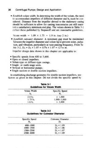
* Establish volute width. In determing the width of the volute, the need
to accommodate impellers of different diameter and ba must be con-
sidered. Distance from the impeller shroud to the stationary casing
should be sufficient to allow for casting inaccuracies yet still main-
tain a satisfactory minimum end play. The values shown in Table 3-1
reflect those published by Stepanoff and are reasonable guidelines,
Volute width = 1.09 x 1.75 = 1.9 in. (say 2 in.)
* Establish cutwater diameter. A minimum gap must be maintained
between the impeller diameter and volute lip to prevent noise, pulsa-
tion, and vibration, particularly at vane passing frequency. From Ta-
7
ble 3-2, D 3 = D 2 x 1.07 = IP/a x 1.07 = 12 /i6 in.
Impeller design data shown in this chapter are applicable to:
• Specific speeds from 400 to 3,600,
« Open or closed impellers.
» Volute-type or diffuser-type casings.
• Single- or multi-stage units.
« Vertical or horizontal pumps.
• Single suction or double suction impellers.
In establishing discharge geometry for double suction impellers, use
factors as given in this chapter. Do not divide the specific speed by
Table 3-1
Guidelines for Volute Width
Volute Width Specific Speed
ba Ns
< 1,000
2.0 b 2
1.75hz 1,000-3,000
1.6b 2 > 3,000
Table 3-2
Guidelines for Cutwater Diameter
Specific Speed Cutwater Diameter
D^
N s
600-1000 D 2 xl.05
1000-1500 D 2 xl.06
1500-2500 D 2 xl.07
2500-4000 D 2 x 1.09