
Page 52 - Centrifugal Pumps 2E
P. 52
38 Centrifugal Pumps: Design and Application
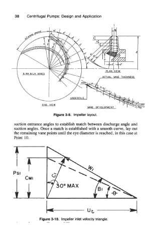
Figure 3-9. Impeller layout.
suction entrance angles to establish match between discharge angle and
suction angles. Once a match is established with a smooth curve, lay out
the remaining vane points until the eye diameter is reached, in this case at
Point 10.
Figure 3-10. Impeller inlet velocity triangle.