
Page 241 - Centrifugal Pumps Design and Application
P. 241
Double-Case Pumps 215
The throttle bushing bore, the shaft under the bushing, or both should
be grooved. To obtain the desired effect, the following design parameters
are varied: the groove cross section, the number of groove starts, the
"hand" of the grooves, and the length of the grooved section. The
grooves reduce leakage for a given running clearance and increase toler-
ance to solid particles in the feedwater. They also reduce the possibility
of seizure if the pump is subjected to severe operating transients, such as
flashing. Shaft sleeves under the throttle bushings are undesirable. They
reduce the ability to resist seizure during severe temperature transients,
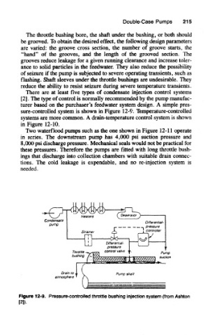
There are at least five types of condensate injection control systems
[2]. The type of control is normally recommended by the pump manufac-
turer based on the purchaser's feedwater system design. A simple pres-
sure-controlled system is shown in Figure 12-9. Temperature-controlled
systems are more common. A drain-temperature control system is shown
in Figure 12-10.
Two waterflood pumps such as the one shown in Figure 12-11 operate
in series. The downstream pump has 4,(XX) psi suction pressure and
8,(MX) psi discharge pressure. Mechanical seals would not be practical for
these pressures. Therefore the pumps are fitted with long throttle bush-
ings that discharge into collection chambers with suitable drain connec-
tions. The cold leakage is expendable, and no re-injection system Is
needed.
Figure 12-0. Pressure-controHed throttle bushing injection system (from Ashton
I2l).