
Page 250 - Centrifugal Pumps Design and Application
P. 250
Doubte-Case Pumps 223
Volute Casings
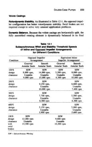
Rotordynamic Stability. As illustrated in Table 12-1, the opposed-impel-
ler configuration has better rotordynamic stability. Swirl brakes are not
required except to solve very unusual application problems.
Dynamic Balance. Because the volute casings are horizontally split, the
folly assembled rotating element is dynamically balanced in its final
Table 12-1
Subsynchronous Whirl and Stability Threshold Speeds
of Inline and Opposed Impeller Arrangements
for Different Conditions
Opposed Impeller Equivalent Inline
Condilion_ Arrangement Impeller Arrangement
Grooved Smooth Grooved Smooth
Annular Seals Annular Seals Annular Seals Annular Seals
Too%sswsswss w ss w ~
design 8,000 rpm, 14,000 rpm, 5,500 rpm, 8,000 rpm,
clearance Unstable Unstable Unstable Unstable
9,000 rpm 15,000 rpm 6,500 rpm 10,000 rpm
200% SSW SSW
design 9,250 rpm, 6,600 rpm,
clearance Unstable Unstable
^ 10,000 rpm LfPJLSEL
300% SSW SSW
design 7,700 rpm, 5,500 rpm,
clearance Unstable Unstable
8,500 rpm 6,300 rpm
400% SSW SSW
design 5,150 rpm, 5,000 rpm,
clearance Unstable Unstable
5,900 rpm MPJ^rjEL.
100% SSW SSW
design 12,000 rpm 9,000 rpm
clearance Unstable Unstable
with 13,500 rpm 10,500 rpm
swirl
brakes
SSW — Subsynchronous Whirling