
Page 49 - Chemical Process Equipment - Selection and Design
P. 49
24 FLOWSHEETS
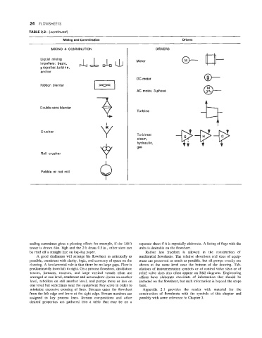
TABLE 2.2-(continosd)
Mixing and Comminution Drivers
MIXING & COMMINUTION DRIVERS
Liquid mixing Motor
impellers: basic,
propeller,turbine,
anchor
DC motor
Ribbon blender
AC motor, 3-phase @-
9
Double cone blender
Turbine
Crusher
Turbines:
steam,
hydraulic,
gas
Roll crusher
Q
Pebble or rod mill
scaling sometimes gives a pleasing effect; for example, if the 150 ft separate sheet if it is especially elaborate. A listing of flags with the
tower is drawn 6 in. high and the 2 ft drum 0.5 in., other sizes can units is desirable on the flowsheet.
be read off a straight line on log-log paper. Rather less freedom is allowed in the construction of
A good draftsman will arrange his flowsheet as artistically as mechanical flowsheets. The relative elevations and sizes of equip-
possible, consistent with clarity, logic, and economy of space on the ment are preserved as much as possible, but all pumps usually are
drawing. A fundamental rule is that there be no large gaps. Flow is shown at the same level near the bottom of the drawing. Tab-
predominantly from left to right. On a process flowsheet, distillation ulations of instrumentation symbols or of control valve sizes or of
towers, furnaces, reactors, and large vertical vessels often are relief valve sizes also often appear on P&I diagrams. Engineering
arranged at one level, condenser and accumulator drums on another offices have elaborate checklists of information that should be
level, reboilers on still another level, and pumps more or less on included on the flowsheet, but such information is beyond the scope
one level but sometimes near the equipment they serve in order to here.
minimize excessive crossing of lines. Streams enter the flowsheet Appendix 2.1 provides the reader with material for the
from the left edge and leave at the right edge. Stream numbers are construction of flowsheets with the symbols of this chapter and
assigned to key process lines. Stream compositions and other possibly with some reference to Chapter 3.
desired properties are gathered into a table that may be on a