
Page 45 - Chemical Process Equipment - Selection and Design
P. 45
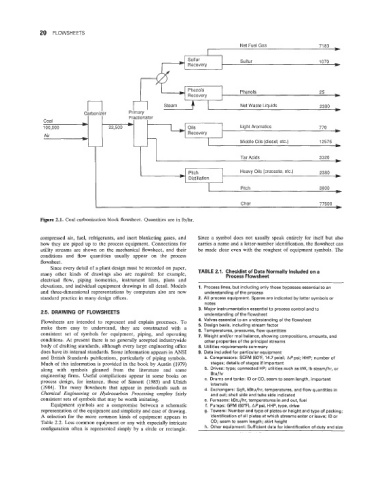
20  FLOWSHEETS

                                                                                 Net Fuel Gas              71 83
                                                                      I                                         c
                                                               Sulfur            Sulfur
                                                               Recovery


                                                               Recovery
                                            Primary  r-7   Steam  +              Phenols                   2380
                                                              I
                                                       Steam
                                                                                 Net Waste Liquids
                                                                                 Net Waste Liquids
                                                                                                           2380
                             Carbonizer     Primary
                                            Fractionator
                                            Fractionator
               Coal
               Coal
               100,000
                                                                                 Light Aromatics
                                                                                                           770
               100,000               22,500                    Oils              Light  Aromatics          770
                                                               Oils
                                                               Recovery
                                                               Recovery
                Air
                Air                                           I            I
                                                                      I  I       Middle  Oils  (diesel,  etc.)   12575
                                                                                 Middle Oils (diesel, etc.)
                                                                                                           12575
                                                                                 Tar Acids                 3320
                                                                Distillation  t   Heavy Oils (creosote, etc.)   2380
                                                                Pitch
                                                              I            1
                                                                      1          Pitch                     3000
                                                                                 Char                      77500
              Figure 2.1.  Coal carbonization block flowsheet. Quantities are in lb/hr
              compressed air,  fuel,  refrigerants,  and inert  blanketing gases, and   Since a  symbol does  not  usually speak  entirely for  itself  but  also
               how they are piped up  to the process equipment.  Connections for   carries a name and a letter-number identification, the flowsheet can
              utility  streams  are  shown on the  mechanical flowsheet, and  their   be  made clear even with  the roughest of  equipment symbols. The
               conditions  and  flow  quantities  usually  appear  on  the  process
               flowsheet.
                  Since every detail of  a plant design must be recorded on paper,
               many  other  kinds  of  drawings  also  are  required:  for  example,   TABLE 2.1.  Checklist of Data Normally Included on a
                                                                            Process Flowsheet
               electrical  flow,  piping  isometrics,  instrument  lines,  plans  and
               elevations, and individual equipment drawings in all detail. Models   1.  Process lines, but including only those bypasses essential to an
               and  three-dimensional representations  by  computers also are now   understanding of the process
               standard practice in many design offices.           2.  All process equipment. Spares are indicated by letter symbols or
                                                                     notes
                                                                   3.  Major instrumentation essential to process control and to
               2.5.  DRAWING OF  FLOWSHEETS                          understanding of the flowsheet
               Flowsheets  are  intended  to  represent  and  explain processes.  To   4.  Valves essential to an understanding of the flowsheet
               make  them  easy  to  understand,  they  are  constructed  with  a   5.  Design basis, including stream factor
                                                                   6.  Temperatures, pressures, flow quantities
               consistent  set  of  symbols  for  equipment,  piping,  and  operating   7.  Weight and/or  mol balance, showing compositions, amounts, and
               conditions. At present  there is no generally accepted industrywide   other properties of the principal streams
               body of  drafting standards,  although every large engineering office   8. Utilities requirements summary
               does have its internal standards. Some information appears in ANSI   9.  Data included for particular equipment
               and British Standards publications, particularly of  piping symbols.   a.  Compressors: SCFM (6OoF, 14.7 psia); APpsi;  HHP;  number of
               Much of  this information is provided in the book by Austin (1979)   stages; details of stages if important
               along  with  symbols  gleaned  from  the  literature  and  some   b.  Drives: type; connected HP; utilities such as kW,  Ib steam/hr, or
               engineering firms.  Useful  compilations appear  in  some books  on   Btu/hr
               process  design,  for  instance,  those  of  Sinnott  (1983)  and  Ulrich   c.  Drums and tanks: ID or OD,  seam to seam length, important
                                                                       internals
               (1984).  The  many  flowsheets  that  appear  in  periodicals  such  as   d.  Exchangers: Sqft, kBtu/hr, temperatures, and flow quantities in
               Chemical  Engineering  or  Hydrocarbon  Processing  employ  fairly   and out; shell side and tube side indicated
               consistent sets of symbols that may be worth imitating.   e.  Furnaces: kBtu/hr, temperatures in and out, fuel
                  Equipment  symbols  are  a  compromise between  a  schematic   f.  Pumps: GPM (60°F),  APpsi, HHP, type, drive
               representation of the equipment and simplicity and ease of  drawing.   g.  Towers: Number and type of plates or height and type of packing;
               A  selection for  the  more  common kinds of  equipment  appears in   identification of all plates at which streams enter or leave;  ID or
               Table 2.2. Less common equipment or any with especially intricate   OD;  seam to seam length; skirt height
               configuration often is  represented  simply by  a circle or rectangle.   h.  Other equipment:  Sufficient data for identification of duty and size