
Page 260 - Chemical engineering design
P. 260
236
CHEMICAL ENGINEERING
The basic components of an automatic trip system are:
1. A sensor to monitor the control variable and provide an output signal when a preset
value is exceeded (the instrument).
2. A link to transfer the signal to the actuator, usually consisting of a system of
pneumatic or electric relays.
3. An actuator to carry out the required action; close or open a valve, switch off a
motor.
A description of some of the equipment (hardware) used is given by Rasmussen (1975).
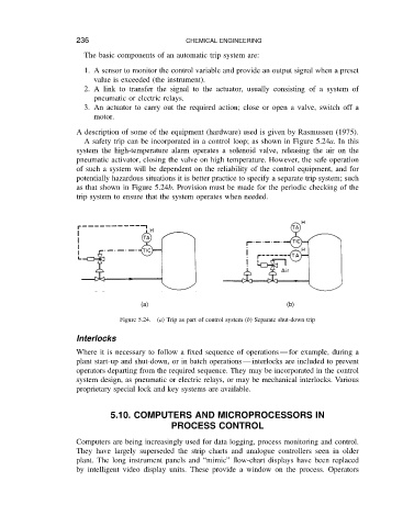
A safety trip can be incorporated in a control loop; as shown in Figure 5.24a.Inthis
system the high-temperature alarm operates a solenoid valve, releasing the air on the
pneumatic activator, closing the valve on high temperature. However, the safe operation
of such a system will be dependent on the reliability of the control equipment, and for
potentially hazardous situations it is better practice to specify a separate trip system; such
as that shown in Figure 5.24b. Provision must be made for the periodic checking of the
trip system to ensure that the system operates when needed.
(a) (b)
Figure 5.24. (a) Trip as part of control system (b) Separate shut-down trip
Interlocks
Where it is necessary to follow a fixed sequence of operations for example, during a
plant start-up and shut-down, or in batch operations interlocks are included to prevent
operators departing from the required sequence. They may be incorporated in the control
system design, as pneumatic or electric relays, or may be mechanical interlocks. Various
proprietary special lock and key systems are available.
5.10. COMPUTERS AND MICROPROCESSORS IN
PROCESS CONTROL
Computers are being increasingly used for data logging, process monitoring and control.
They have largely superseded the strip charts and analogue controllers seen in older
plant. The long instrument panels and “mimic” flow-chart displays have been replaced
by intelligent video display units. These provide a window on the process. Operators