
Page 172 - Chemical process engineering design and economics
P. 172
Process Heat Transfer 155
Flow Tub*
O.D..
Pitch
Pitch
In-Lim Square Pitch Diamond Squort Pitch
Flow
L- Ligamtnt
Trionqulqf Pitch In-Lin* Triangular Pitch
(Apex Vertical) (Ap*x Horizontal)
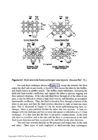
Figure 4.2 Shell-and-tube heat-exchanger tube layouts. (Source Ref. 15.)
For each heat exchanger shown in Figure 4.1, except the reboiler, the fluid
enters the shell side in one nozzle, is forced to flow across the tubes by the baffles,
and finally leaves in another nozzle. The baffles create turbulence, increasing the
shell-side heat-transfer coefficient, and support the tubes to prevent sagging and
flow induced vibrations. If the tube-side fluid flows through all of the tubes in one
pass, it may be difficult to obtain a high fluid velocity and therefore an acceptable
heat-transfer coefficient. Thus, the fluid is forced to flow through a fraction of the
tubes in one pass, and then the fluid reverses direction to make at least one more
pass. This is illustrated in Figure 4.1 for the inside-split-backing-ring heat ex-
changer, where a pass partition divides the tubes into two sections. A heat ex-
changer with one shell pass and two or more tube passes is referred to as a 1-2 heat
exchanger. It is thus seen that the flow is not purely countercurrent. In the shell
side there is crossflow, and in the tube side the flow is countercurrent to the shell
fluid in one direction and then cocurrent to the shell fluid in the other direction.
The seal type selected depends on the pressure and temperature in the shell
and tubes. Three types of seals employed in shell-and-tube heat exchangers,
Copyright © 2003 by Taylor & Francis Group LLC