
Page 176 - Chemical process engineering design and economics
P. 176
158 Chapter 4
For the outside-packed lantern ring, the shell and tube-side fluids will not mix
within the shell. If the packing leaks, then the liquid will flow through the weep
holes in the lantern ring and drop to the floor. This design will not be satisfactory
for dangerous liquids unless a means for collecting the liquid safely is devised
This particular design is limited to 11.4 bar (11.3 arm) and 160°C (320 °F).
When higher shell-side temperatures and pressures than are attainable with a
packing-type seal are required, then the inside-split backing-ring design is used.
This design uses only gaskets as shown in Figure 4.1. To remove the tube bundle
for maintenance requires removing the front end, and the split ring, and the float-
ing-head cover at the back end. Because no seal can be guaranteed to be leak
proof, there is the possibility that shell-side and tube-side fluids could mix so that
this design is limited to fluids that can mix without creating a hazard.
The final heat-exchanger design considered is the kettle-type reboiler,
shown in Figure 4.1. The boiling fluid, which could be a refrigerant or other proc-
ess fluids, is placed on the shell side. In this design, the shell is enlarged to allow
some separation of entrained liquid droplets in the vapor. Also, the tube bundle
can be removed for maintenance. As was the case for the split-ring design, the
kettle reboiler should not be used if mixing of the shell-side and tube-side fluids
creates a hazard. The tubes in the kettle reboiler are free to expand in the shell.
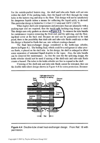
If mixing of the shell-side and tube-side fluids cannot be tolerated, then use
the double tube-sheet design shown in Figure 4.4 for extra protection. Because
Light-gage shroud for
collection or sealing
\ Channel
flange
Figure 4.4 Double-tube sheet heat-exchanger design. From Ref. 18 with
permission.
Copyright © 2003 by Taylor & Francis Group LLC