
Page 179 - Chemical process engineering design and economics
P. 179
Process Heat Transfer 161
quired to transfer a specified amount of heat. This formula, which may be used
for both countercurrent and cocurrent flow, is derived in a number of texts (for
example, see Reference 4.22). Although countercurrent flow is the most efficient,
cocurrent flow is used when it is necessary to limit the final temperature of a heat
sensitive material. Cocurrent flow is also used when a rapid change in temperature
is needed (quenching) [8].
The logarithmic-mean temperature difference, (At) LM, is defined by
(t 4 -ti)-(t 3 -t 2 )
(At) LM = ————————— (4-2)
(U-t.)
ill ———————
(ts-t 2 )
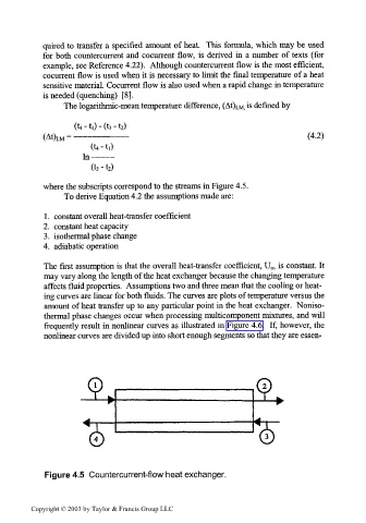
where the subscripts correspond to the streams in Figure 4.5.
To derive Equation 4.2 the assumptions made are:
1. constant overall heat-transfer coefficient
2. constant heat capacity
3. isothermal phase change
4. adiabatic operation
The first assumption is that the overall heat-transfer coefficient, U, is constant. It
0
may vary along the length of the heat exchanger because the changing temperature
affects fluid properties. Assumptions two and three mean that the cooling or heat-
ing curves are linear for both fluids. The curves are plots of temperature versus the
amount of heat transfer up to any particular point in the heat exchanger. Noniso-
thermal phase changes occur when processing multicomponent mixtures, and will
frequently result in nonlinear curves as illustrated in Figure 4.6. If, however, the
nonlinear curves are divided up into short enough segments so that they are essen-
Figure 4.5 Countercurrent-flow heat exchanger.
Copyright © 2003 by Taylor & Francis Group LLC