
Page 182 - Chemical process engineering design and economics
P. 182
164 Chapter 4
ti-t 2
v-^ R=-
(
«— t»-t 3
/"->
T tl-t 3
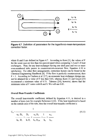
Figure 4.7 Definition of parameters for the logarithmic-mean-temperature
correction factor.
where R and S are defined in Figure 4.7. According to Kern [1], the values of F
for the worst case are less than two percent apart when comparing 1 -2 and 1 -8 heat
exchangers. Thus, for any heat exchanger having one shell pass and two or more
even-numbered tube passes in countercurrent-cocurrent flow, Equation 4.10 is
satisfactory. For other flow arrangements, correction factors can be found in the
Chemical Engineering Handbook [6]. If the flow is perfectly countercurrent, then
F = 1. According to Coulson et al. [17], an economic heat exchanger design can-
not be attained for a value of F less than 0.85, whereas Kern [1] and Goyal [23]
recommend a minimum value of 0.75. Taborex [24], however, shows that the
minimum value of F varies with R and S. We will use 0.85.
Overall Heat-Transfer Coefficients
The overall heat-transfer coefficient, defined by Equation 4.11, is derived in a
number of texts (see for example Reference 4.22). If the heat transferred is based
on the outside area of the tube, then the overall heat-transfer coefficient is
1
U 0 =- (4.11)
X f i DO DO X w DO X fo
k fi D; hjDj k w D LM ho k fo
Copyright © 2003 by Taylor & Francis Group LLC