
Page 181 - Chemical process engineering design and economics
P. 181
Process Heat Transfer 163
where n is the number of segments. After solving Equation 4.6 for Q, we find that
n
—————————————————————— (4.7)
Q = U 0 A 0
l/(At) LMi + l/(At) LM2 + • • + l/(At) LMn
•
The expression to the right of A 0 is an effective logarithmic-mean tempera-
ture difference. Thus,
Q=U 0A 0(At) LM,eff
Correction Factor for Non-countercurrent Flow
It was seen from the discussion of heat exchangers that the fluid streams are not
strictly countercurrent. Baffles on the shell side induce crossflow, and in a two-
tube-pass heat exchanger both countercurrent and cocurrent flow occur. To ac-
count for deviations from countercurrent flow, the logarithmic-mean temperature
difference is multiplied by a correction factor, F. Thus,
Q = U 0 A 0 F(At) LM (4.9)
An equation for the correction factor can be derived with the following as-
sumptions:
1. adiabatic operation
2. well mixed shell-side fluid
3. the heat-transfer surface area is the same for each tube pass
4. constant overall heat-transfer coefficient
5. constant heat capacity
6. no phase change for either fluid
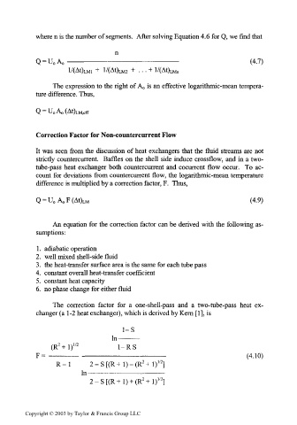
The correction factor for a one-shell-pass and a two-tube-pass heat ex-
changer (a 1-2 heat exchanger), which is derived by Kern [1], is
1-S
i n____
111
————————
2
(R +l) 1/2 1-R S
F= —————— ————————————————— (4.10)
2
2
R-l 2-S[(R+l)-(R +l)" ]
In ——————————————
Copyright © 2003 by Taylor & Francis Group LLC