
Page 249 - Chemical process engineering design and economics
P. 249
230 Chapter 5
Expanders
The energy from high-pressure gas streams may be used to drive compressors or
pumps. High pressure gases range in temperature from the low-temperature cryo-
genic fluids to high-temperature combustion gases. The energy source could be
the process stream itself or an external working fluid such as steam. Frequently,
the energy source is high-pressure steam, but the process engineer should seek
opportunities to conserve energy by utilizing the energy from high-pressure proc-
ess streams whenever possible. In either case, the energy for compression or
pumping is obtained by expanding the gas through an expander. Like dynamic
compressors, gas expanders are available in either the radial or axial-flow design,
where the radial-flow design is used for low flow rates and high-pressure differ-
ences and the axial-flow types at high flow rates and low-pressure differences (1 to
40 bar) (0.9869 to 39.5 arm) [28].
The radial-flow expander consists of inflow and outflow types. In the ra-
dial-outflow type, the gas flows from the center to periphery of the impeller. The
radial-outflow expander is used for very low enthalpy drops, 58 to 70 kJ/kg (25 to
30 Btu/lb) per stage [29]. The radial-inflow expander is similar to a centrifugal
compressor used in reverse, i.e., the gas flows radially inward from the periphery
of the impeller, exhausting approximately axially. Most radial turbines are of the
inflow type. One example of the radial outflow type is the Ljungstrom turbine,
which usually uses steam in small in-house generating plants, producing 10 to 35
MW (13,400 to 46,900 hp) of power [30]. Similarly, the axial expander resembles
an axial compressor where the gas flows through an annular passage in a direction
that is substantially parallel to the axis of the shaft. In both cases, however, the
expander blade design differs from the compressor blade design. An expander
stage consists of a nozzle followed by a rotor. The purpose of a nozzle is to accel-
erate a fluid, converting pressure into kinetic energy, and then guide the gas into
the rotor where kinetic energy is converted into work. The gas velocity varies
from above to below the speed of sound. For a radial flow expander, the nozzle
may be a fixed set of vanes, a variable set of vanes, or no vanes at all [27]. A ra-
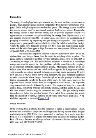
dial-flow expander is shown in Figure 5.18.
Steam Turbines
If the working fluid is steam, then the expander is called a steam turbine. Steam
turbines are available as single and multistage units having several blade designs
and arrangements [31]. If the power generated is too large for a single stage tur-
bine, or if it is necessary to expand the steam more than once to improve the tur-
bine efficiency, then use a multistage turbine. Inlet steam is limited to about 42 bar
(615 psia) and 440 °C (750 °F) [31].
Copyright © 2003 by Taylor & Francis Group LLC