
Page 246 - Chemical process engineering design and economics
P. 246
Compressors, Pumps, and Turbines 227
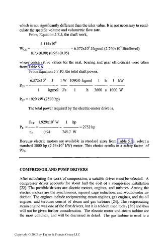
which is not significantly different than the inlet value. It is not necessary to recal-
culate the specific volume and volumetric flow rate.
From, Equation 5.7.5, the shaft work,
4.1 14x1 0 6
6
3
WCN = ————————————— = 6.372x1 0 J/kgmol (2.740x1 0 Btu/lbmol)
0.73 (0.98) (0.95) (0.95)
where conservative values for the seal, bearing and gear efficiencies were taken
from Table 5.6.
From Equation 5.7.10, the total shaft power,
6.372xl0 6 J 1 W 1090.0 kgmol 1 h 1 kW
1 kgmol J/s 1 h 3600 s 1000 W
P CP = 1929 kW (2590 hp)
The total power required by the electric-motor drive is,
6
PCP 1.929xl0 W 1 hp
P E = —— = —————— - ————— = 2752 hp
TIE 0.94 745.7 W
Because electric motors are available in standard sizes from Table 5. la, select a
3
standard 3000 hp (2.24x1 0 kW) motor. This choice results in a safety factor of
9%.
COMPRESSOR AND PUMP DRIVERS
After calculating the work of compression, a suitable driver must be selected. A
compressor driver accounts for about half the cost of a compressor installation
[22]. The possible drivers are electric motors, engines, and turbines. Among the
electric motors are the synchronous, squirrel cage induction, and wound-rotor in-
duction. The engines include reciprocating steam engines, gas engines, and the oil
engines, and turbines consist of steam and gas turbines [24]. The reciprocating
steam engine was one of the first drivers, but it is seldom used today [36] and thus
will not be given further consideration. The electric motor and steam turbine are
the most common, and will be discussed in detail. The gas turbine is used to a
Copyright © 2003 by Taylor & Francis Group LLC