
Page 218 - Civil Engineering Formulas
P. 218
CONCRETE FORMULAS 153
In usual design work on retaining walls the sum of the righting moments
and the sum of the overturing moments about the toe are found. It is assumed
by designers that if the retaining wall is overturned, it will overturn about the
toe of the retaining wall. Designers then apply a safety factor thus:
Retaining wall righting moment 1.5 (overturning moment)
The 1.5 safety factor is a common value amongst designers.
CANTILEVER RETAINING WALLS
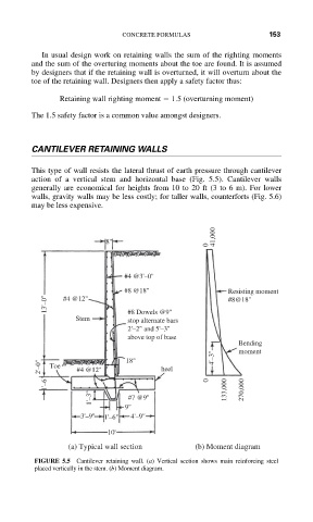
This type of wall resists the lateral thrust of earth pressure through cantilever
action of a vertical stem and horizontal base (Fig. 5.5). Cantilever walls
generally are economical for heights from 10 to 20 ft (3 to 6 m). For lower
walls, gravity walls may be less costly; for taller walls, counterforts (Fig. 5.6)
may be less expensive.
41,000
8"
0
#4 @3'–0"
#8 @18" Resisting moment
13'–0" #4 @12" #8@18"
Stem #8 Dowels @9"
stop alternate bars
2'–2" and 5'–3"
above top of base
Bending
moment
2'–0" Toe #4 @12" 18" heel 4'–3"
1'–6" 0 133,000 270,000
1'–3" #7 @9"
9"
3'–9" 1'–6" 4'–9"
10'
(a) Typical wall section (b) Moment diagram
FIGURE 5.5 Cantilever retaining wall. (a) Vertical section shows main reinforcing steel
placed vertically in the stem. (b) Moment diagram.