
Page 220 - Civil Engineering Formulas
P. 220
CONCRETE FORMULAS 155
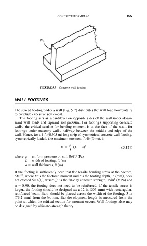
Wall
FIGURE 5.7 Concrete wall footing.
WALL FOOTINGS
The spread footing under a wall (Fig. 5.7) distributes the wall load horizontally
to preclude excessive settlement.
The footing acts as a cantilever on opposite sides of the wall under down-
ward wall loads and upward soil pressure. For footings supporting concrete
walls, the critical section for bending moment is at the face of the wall; for
footings under masonry walls, halfway between the middle and edge of the
wall. Hence, for a 1-ft (0.305-m) long strip of symmetrical concrete-wall footing,
symmetrically loaded, the maximum moment, ft lb (N m), is
p
M (L a) 2 (5.121)
8
2
where p uniform pressure on soil, lb/ft (Pa)
L width of footing, ft (m)
a wall thickness, ft (m)
If the footing is sufficiently deep that the tensile bending stress at the bottom,
2
6M/t , where M is the factored moment and t is the footing depth, in (mm), does
2
not exceed 5 f c , where f is the 28-day concrete strength, lb/in (MPa) and
c
0.90, the footing does not need to be reinforced. If the tensile stress is
larger, the footing should be designed as a 12-in (305-mm) wide rectangular,
reinforced beam. Bars should be placed across the width of the footing, 3 in
(76.2 mm) from the bottom. Bar development length is measured from the
point at which the critical section for moment occurs. Wall footings also may
be designed by ultimate-strength theory.