
Page 310 - Civil Engineering Formulas
P. 310
244 CHAPTER NINE
W
M 1 M 2
3 3
M 1 M 2
W
H 2
1 2 1 H 2
H H 1
V 2 V
V 1 V
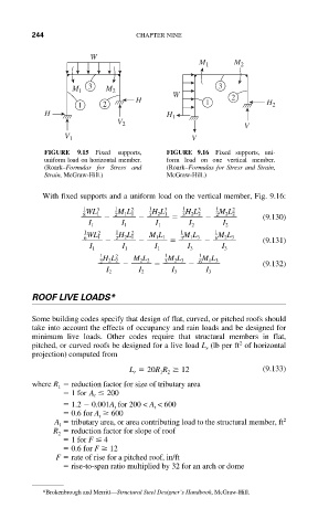
FIGURE 9.15 Fixed supports, FIGURE 9.16 Fixed supports, uni-
uniform load on horizontal member. form load on one vertical member.
(Roark–Formulas for Stress and (Roark–Formulas for Stress and Strain,
Strain, McGraw-Hill.) McGraw-Hill.)
With fixed supports and a uniform load on the vertical member, Fig. 9.16:
1 3 1 2 1 3 1 3 1 2
8 WL 1 2 M 1 L 1 3 H 2 L 1 3 H 2 L 2 2 M 2 L 2
(9.130)
I 1 I 1 I 1 I 2 I 2
1 2 1 2 1 1
6 WL 1 2 H 2 L 1 M 1 L 1 3 M 1 L 3 6 M 2 L 3 (9.131)
I 1 I 1 I 1 I 3 I 3
1 2 1 1
2 H 2 L 2 M 2 L 2 3 M 2 L 3 6 M 1 L 3
(9.132)
I 2 I 2 I 3 I 3
ROOF LIVE LOADS*
Some building codes specify that design of flat, curved, or pitched roofs should
take into account the effects of occupancy and rain loads and be designed for
minimum live loads. Other codes require that structural members in flat,
2
pitched, or curved roofs be designed for a live load L (lb per ft of horizontal
r
projection) computed from
L r 20R 1 R 2 12 (9.133)
where R reduction factor for size of tributary area
1
1 for A t 200
1.2 0.001A for 200 < A < 600
t
t
0.6 for A 600
t
A tributary area, or area contributing load to the structural member, ft 2
l
R reduction factor for slope of roof
2
1 for F 4
0.6 for F 12
F rate of rise for a pitched roof, in/ft
rise-to-span ratio multiplied by 32 for an arch or dome
*Brokenbrough and Merritt—Structural Steel Designer’s Handbook, McGraw-Hill.