Page 320 - Civil Engineering Formulas
P. 320

254                     CHAPTER TEN

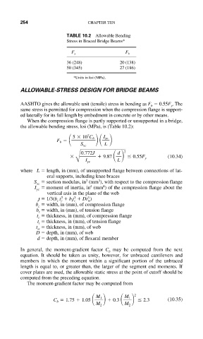
                           TABLE 10.2 Allowable Bending
                           Stress in Braced Bridge Beams*

                             F y                F b
                           36 (248)           20 (138)
                           50 (345)           27 (186)
                              *Units in ksi (MPa).

           ALLOWABLE-STRESS DESIGN FOR BRIDGE BEAMS

           AASHTO gives the allowable unit (tensile) stress in bending as F   0.55F . The
                                                                y
                                                         b
           same stress is permitted for compression when the compression flange is support-
           ed laterally for its full length by embedment in concrete or by other means.
             When the compression flange is partly supported or unsupported in a bridge,
           the allowable bending stress, ksi (MPa), is (Table 10.2):
                               5   10 C b
                                   7
                                        I yc
                        F b
                                S xc     L
                                0.772J       d  2
                                        9.87        0.55F y    (10.34)
                              B I yc         L
           where L   length, in (mm), of unsupported flange between connections of lat-
                    eral supports, including knee braces
                                  3
                                       3
                S   section modulus, in (mm ), with respect to the compression flange
                 xc
                                        4
                                    4
                I   moment of inertia, in (mm ) of the compression flange about the
                yc
                    vertical axis in the plane of the web
                         3
                                   3
                              3
                 J   1/3(b t   b t   Dt )
                                   w
                             t c
                        c c
                b   width, in (mm), of compression flange
                 c
                b   width, in (mm), of tension flange
                 t
                 t   thickness, in (mm), of compression flange
                 c
                 t   thickness, in (mm), of tension flange
                 t
                t   thickness, in (mm), of web
                 w
                D   depth, in (mm), of web
                 d   depth, in (mm), of flexural member
           In general, the moment-gradient factor  C may be computed from the next
                                          b
           equation. It should be taken as unity, however, for unbraced cantilevers and
           members in which the moment within a significant portion of the unbraced
           length is equal to, or greater than, the larger of the segment end moments. If
           cover plates are used, the allowable static stress at the point of cutoff should be
           computed from the preceding equation.
             The moment-gradient factor may be computed from
                                                   2
                                                M 1
                                      M 1
                       C b   1.75   1.05    0.3       2.3      (10.35)
                                      M 2       M 2
   315   316   317   318   319   320   321   322   323   324   325