
Page 282 - Complete Wireless Design
P. 282
Filter Design
Filter Design 281
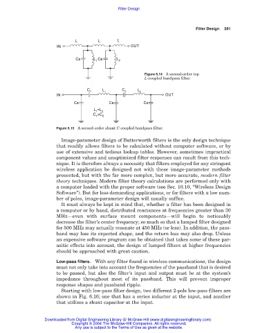
Figure 6.14 A second-order top
L-coupled bandpass filter.
Figure 6.15 A second-order shunt C-coupled bandpass filter.
Image-parameter design of Butterworth filters is the only design technique
that readily allows filters to be calculated without computer software, or by
use of extensive and tedious lookup tables. However, sometimes impractical
component values and unoptimized filter responses can result from this tech-
nique. It is therefore always a necessity that filters employed for any stringent
wireless application be designed not with these image-parameter methods
presented, but with the far more complex, but more accurate, modern filter
theory techniques. Modern filter theory calculations are performed only with
a computer loaded with the proper software (see Sec. 10.10, “Wireless Design
Software”). But for less-demanding applications, or for filters with a low num-
ber of poles, image-parameter design will usually suffice.
It must always be kept in mind that, whether a filter has been designed in
a computer or by hand, distributed reactances at frequencies greater than 30
MHz—even with surface mount components—will begin to noticeably
decrease the filter’s center frequency; so much so that a lumped filter designed
for 500 MHz may actually resonate at 450 MHz (or less). In addition, the pass-
band may lose its expected shape, and the return loss may also drop. Unless
an expensive software program can be obtained that takes some of these par-
asitic effects into account, the design of lumped filters at higher frequencies
should be approached with great caution.
Low-pass filters. With any filter found in wireless communications, the design
must not only take into account the frequencies of the passband that is desired
to be passed, but also the filter’s input and output must be at the system’s
impedance throughout most of its passband. This will prevent improper
response shapes and passband ripple.
Starting with low-pass filter design, two different 2-pole low-pass filters are
shown in Fig. 6.16; one that has a series inductor at the input, and another
that utilizes a shunt capacitor at the input.
Downloaded from Digital Engineering Library @ McGraw-Hill (www.digitalengineeringlibrary.com)
Copyright © 2004 The McGraw-Hill Companies. All rights reserved.
Any use is subject to the Terms of Use as given at the website.