
Page 281 - Complete Wireless Design
P. 281
Filter Design
280 Chapter Six
4. A top L-coupled bandpass filter (Fig. 6.14) is similar to the above top C-cou-
pled filter, except that in this case the roles of the inductors and the capac-
itors are reversed. This topology is also unsymmetrical, but the lower
frequency has more of a gradual slope, while the upper frequency has a
steeper skirt.
5. A shunt C-coupled bandpass filter (Fig. 6.15) is utilized for filters requiring
30 percent or less of bandwidth. Each inductor in this filter type is equal in
value, while the series capacitors are typically quite close in value to each
other. This is also an unsymmetrical filter: The lower cutoff frequency is not
as steep as the upper frequency skirt.
6.1.3 Image-parameter design
Since the proliferation of very low cost filter design software for the average
personal computer, there is really little need to hand-calculate lumped filter
values. However, for completeness, easy-to-design high-pass, low-pass, and
bandpass filters will be demonstrated in the very versatile and popular
Butterworth response characteristic, using image parameters as presented
by Gottlieb.
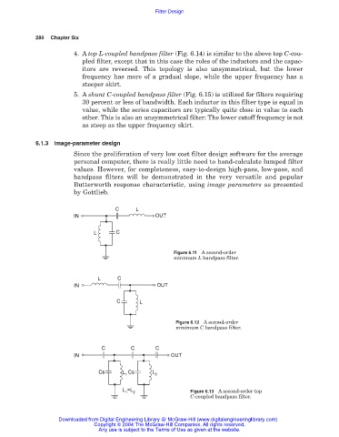
Figure 6.11 A second-order
minimum L bandpass filter.
Figure 6.12 A second-order
minimum C bandpass filter.
Figure 6.13 A second-order top
C-coupled bandpass filter.
Downloaded from Digital Engineering Library @ McGraw-Hill (www.digitalengineeringlibrary.com)
Copyright © 2004 The McGraw-Hill Companies. All rights reserved.
Any use is subject to the Terms of Use as given at the website.